Theory of Operation T400 Ozone Analyzer Operator’s Manual
292
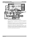
Thermistor(s) – Photometer Lamp
Temperature and Optional IZS O
3
Generator Lamp Temperature)
RELAY PCA
DC
Control
Logic
Preamplifiers
and Signal
Conditioning
MOTHERBOARD
A/D
Converter
(V/F)
CPU
Themocouple(s)
(used on Optional Metal
Wool Scrubber)
DC HEATERS
(UV LAMP Heaters)
THERMOCOUPLE
CONFIGURATION
JUMPER
(JP5)
Cold Junction
Compensation
Solid State
AC Relays
AC HEATER
(optional
Metal Wool Scrubber)
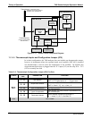
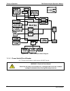
Figure 13-11: Heater Control Loop Block Diagram.
13.3.4.5. Thermocouple Inputs and Configuration Jumper (JP5)
In its base configuration, the T400 analyzer does not include any thermocouple sensors,
however in instruments where the optional metal wool scrubber (OPT-68) is installed
one thermocouple is used to sense the temperature of the scrubber. By default, this
single thermocouple input is plugged into the TC1 input (J15) on the relay PCA. TC2
(J16) is currently not used.
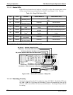
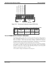
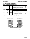
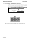
Table 13-2: Thermocouple Configuration Jumper (JP5) Pin-Outs
TC INPUT
JUMPER
PAIR
DESCRIPTION FUNCTION
1 – 11
Gain Selector
Selects preamp gain factor for J or K TC
OUT = K TC gain factor; IN = J TC gain factor
2 – 12
Output Scale Selector
Selects preamp gain factor for J or K TC
OUT = 10 mV / °C; IN = 5 mV / °C
3 – 13
Type J Compensation
When present, sets Cold Junction Compensation for J
type Thermocouple
4 – 14
Type K Compensation
When present, sets Cold Junction Compensation for K
type Thermocouple
TC1
5 – 15
Termination Selector
Selects between Isolated and grounded TC
IN = Isolate TC; OUT = Grounded TC
TC2
NOT USED
06870C DCN6332


