


Theory of Operation T400 Ozone Analyzer Operator’s Manual
290
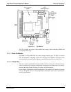
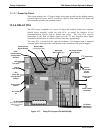
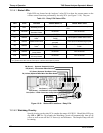
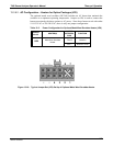
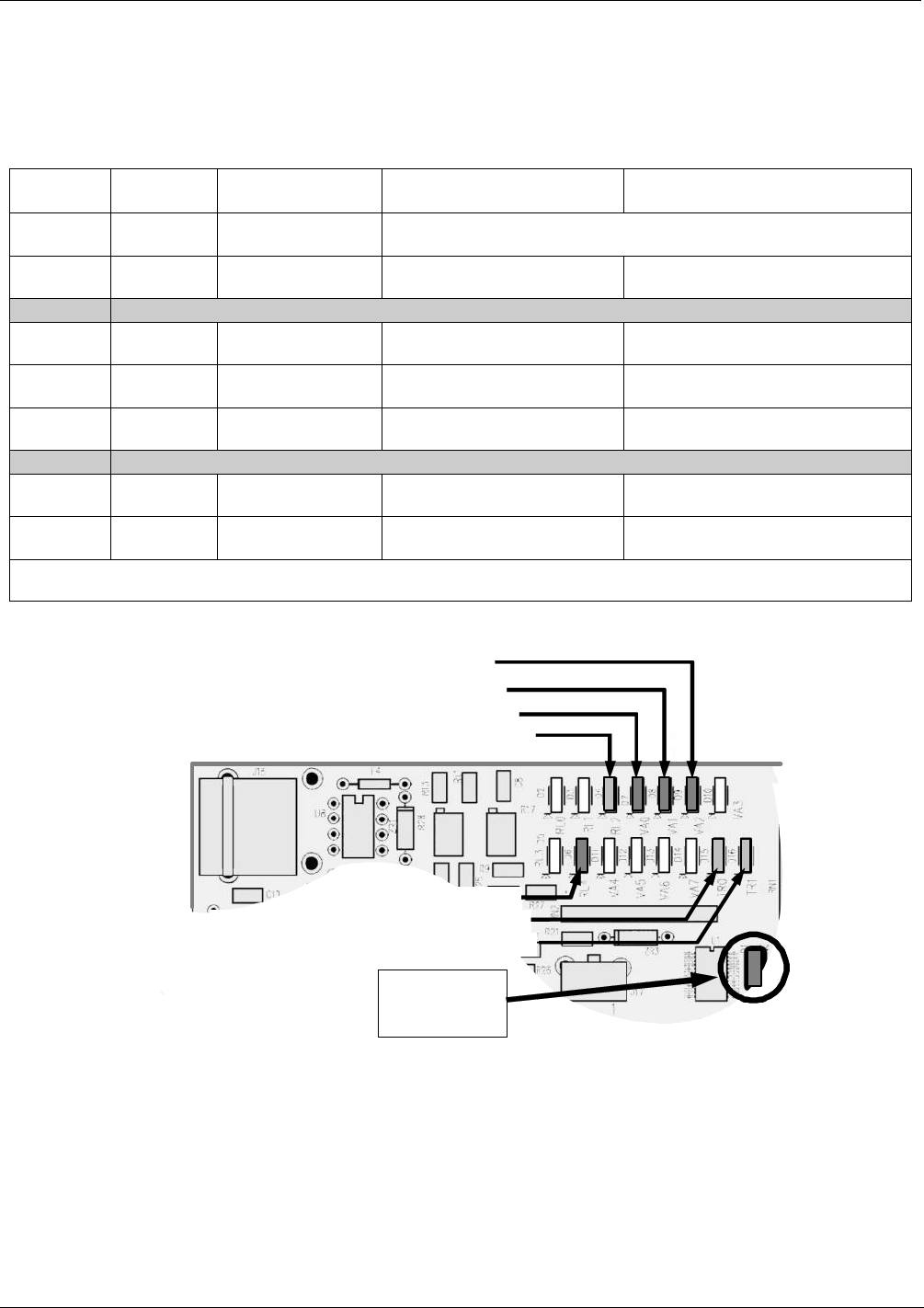
13.3.4.1. Status LEDs
Eight LEDs are located on the Analyzer’s relay PCA to show the current status on the
various control functions performed by the relay PCA (see Figure 13-10). They are:
Table 13-1: Relay PCA Status LEDs
LED Color Function Status When Lit Status When Unlit
D1 RED Watchdog Circuit
Cycles On/Off Every 3 Seconds under direct control of the analyzer’s
CPU.
D2
1
YELLOW
Metal Wool
Scrubber Heater
HEATING NOT HEATING
D3 – D6 SPARE
D7 GREEN
Zero/Span Gas
Valve
1
Valve Open to SPAN GAS
FLOW
Valve Open to ZERO GAS FLOW
D8 GREEN Measure/Ref Valve
Valve Open to REFERENCE
gas path
Valve Open to MEASURE gas path
D9
GREEN
Sample/Cal Gas
Valve
2
Valve Open to CAL GAS
FLOW
Valve Open to SAMPLE GAS
FLOW
D10-D14 SPARE
D15 GREEN
Photometer UV
Lamp Heater
HEATING NOT HEATING
D16 GREEN
IZS O
3
Generator
UV Lamp Heater
HEATING NOT HEATING
1
Only present when the Z/S valve option is installed.
2
Only present when either the Z/S valve option or the IZS valve option is present.
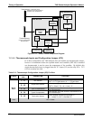
D8 (Green) – Photometer Meas/Ref Valve
D15 (Green) - Photometer Lamp Heater
D16 (Green – IZS O
3
Generator Lamp Heater
D7 (Green) Optional Zero/Span Valve
D6 (Green ) – GPT Valve
D9 (Green) – Optional Sample/Cal Valve
D1 (RED)
Watchdog
Indicator
D2 (Yellow) Optional Metal Wool Scrubber Heater
Figure 13-10: Status LED Locations – Relay PCA
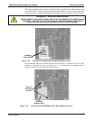
13.3.4.2. Watchdog Circuitry
Special circuitry on the relay PCA watches the status of LED D1. Should this LED ever
stay ON or OFF for 30 seconds, the Watchdog Circuit will automatically shut off all
valves as well as turn off the UV Source (s) and all heaters. The Sample Pump will still
be running.
06870C DCN6332