Teledyne API – Model T400 Photometric Ozone Analyzer Getting Started
47
3.3.1.6. Connecting the Control Inputs
The analyzer is equipped with three digital control inputs that can be used to activate the
To remotely activate the zero and span calibration modes, several digital control inputs
are provided through a 10-pin connector labeled CONTROL IN on the analyzer’s rear
panel.
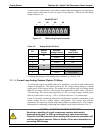
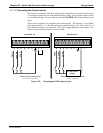
There are two methods for energizing the control inputs. The internal +5V available
from the pin labeled “+” is the most convenient method (Figure 3-10, left). However, if
full isolation is required, an external 5 VDC power
supply should be used (Figure 3-10,
right) to ensure that these inputs are truly isolated.
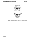
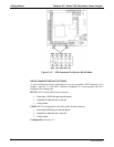
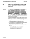
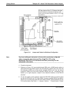
CONTROL IN
A B C D E F U
+
LO SPAN
ZERO
SPAN
CONTROL IN
A B C D E F U
+
LO SPAN
ZERO
SPAN
-
+
5 VDC Power
Supply
Local Power Connections
(non-isolated configuration)
External Power Connections
(isolated configuration)
Figure 3-10: Energizing the T400 Control Inputs
06870C DCN6332


