


Teledyne API – Model T400 Photometric Ozone Analyzer Getting Started
43
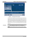
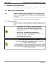
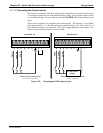
3.3.1.2. Connecting Analog Inputs (Option)
The Analog In connector is used for connecting external voltage signals from other
instrumentation (such as meteorological instruments) and for logging these signals in the
analyzer’s internal DAS. The input voltage range for each analog input is 0-10 VDC.
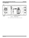
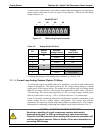
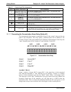
Figure 3-6: Analog In Connector
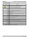
Pin assignments for the Analog In connector are presented in Table 3-4.
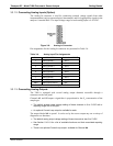
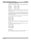
Table 3-4: Analog Input Pin Assignments
PIN DESCRIPTION DAS PARAMETER
1
1 Analog input # 1 AIN 1
2 Analog input # 2 AIN 2
3 Analog input # 3 AIN 3
4 Analog input # 4 AIN 4
5 Analog input # 5 AIN 5
6 Analog input # 6 AIN 6
7 Analog input # 7 AIN 7
8 Analog input # 8 AIN 8
GND Analog input Ground N/A
1
See Section 7.6 for details on setting up the DAS.
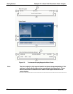
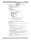
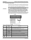
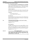
3.3.1.3. Connecting Analog Outputs
The T400 is equipped with several analog output channels accessible through a
connector on the rear panel.
Channels A1 and A2 output a signal that is proportional to the O
3
concentration of the
sample gas.
The default analog output voltage setting of these channels is 0 to 5 VDC with a
reporting range of 0 to 500 ppb.
An optional Current Loop output is available for each.
The output labeled A4 is special. It can be set by the user to output any one a variety of
diagnostic test functions.
The default analog output voltage setting of these channels is also 0 to 5 VDC.
See Section 5.10.1.9 for a list of available functions
and their associated reporting
range.
There is no optional Current Loop output available for Channel A4.
06870C DCN6332