xiii
TABLE OF CONTENTS
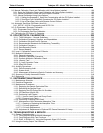
1. INTRODUCTION, FEATURES AND OPTIONS ................................................................. 25
1.1. Overview .......................................................................................................................................................25
1.2. Features ........................................................................................................................................................25
1.3. Options..........................................................................................................................................................26
2. SPECIFICATIONS, APPROVALS & COMPLIANCE ......................................................... 29
2.1. Specifications ................................................................................................................................................29
2.2. EPA Equivalency Designation.......................................................................................................................31
2.3. Approvals and Certifications .........................................................................................................................32
2.3.1. Safety.....................................................................................................................................................32
2.3.2. EMC .......................................................................................................................................................32
2.3.3. Other Type Certifications .......................................................................................................................32
3. GETTING STARTED .......................................................................................................... 33
3.1. Unpacking the T400 Analyzer.......................................................................................................................33
3.1.1.1. Ventilation Clearance .....................................................................................................................34
3.2. Instrument layout...........................................................................................................................................35
3.2.1. Front Panel ............................................................................................................................................35
3.2.2. Rear Panel.............................................................................................................................................39
3.2.3. Internal Chassis Layout .........................................................................................................................41
3.3. Connections and Setup.................................................................................................................................42
3.3.1. Electrical Connections ...........................................................................................................................42
3.3.1.1. Connecting Power ..........................................................................................................................42
3.3.1.2. Connecting Analog Inputs (Option) ................................................................................................43
3.3.1.3. Connecting Analog Outputs ...........................................................................................................43
3.3.1.4. Current Loop Analog Outputs (Option 41) Setup...........................................................................44
3.3.1.5. Connecting the Status Outputs ......................................................................................................46
3.3.1.6. Connecting the Control Inputs........................................................................................................47
3.3.1.7. Connecting the Concentration Alarm Relay (Option 61)................................................................48
3.3.1.8. Connecting the Communications Interfaces ..................................................................................50
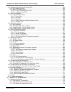
3.3.2. Pnenumatic Connections.......................................................................................................................56
3.3.2.1. About Zero Air and Calibration Gas ...............................................................................................56
3.3.2.2. Pneumatic Setup for Basic Configuration.......................................................................................59
3.3.2.3. Pneumatic Setup for the T400 Analyzer with Internal Zero/Span Option (IZS) .............................60
3.3.3. Pneumatic Setups for Ambient Air Monitoring.......................................................................................61
3.3.3.1. Pneumatic Set Up for T400’s Located in the Same Room Being Monitored .................................61
3.3.3.2. Pneumatic Set Up for T400’s Monitoring Remote Locations .........................................................62
3.4. Startup, Functional Checks, and Initial Calibration .......................................................................................63
3.4.1. Start Up..................................................................................................................................................63
3.4.2. Warning Messages ................................................................................................................................63
3.4.3. Functional Check ...................................................................................................................................65
3.4.4. Initial Calibration ....................................................................................................................................65
3.4.4.1. Interferents for O
3
Measurement....................................................................................................65
3.4.5. Initial Calibration Procedure for T400 Analyzers without Options .........................................................66
3.4.5.1. Verifying the T400 Reporting Range Settings................................................................................66
3.4.5.2. Verify the Expected O
3
Span Gas Concentration:..........................................................................67
3.4.5.3. Initial Zero/Span Calibration Procedure: ........................................................................................69
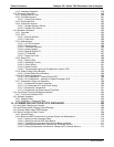
3.5. Configuring the Internal Zero/Span Option (IZS) ..........................................................................................70
3.5.1. Verify the O
3
Generator and Expected O
3
Span Concentration Settings..............................................70
3.5.2. Setting the O
3
Generator Low-Span (Mid Point) Output Level ..............................................................71
3.5.3. Turning on the Reference Detector Option............................................................................................72
3.5.4. Initial Calibration and Conditioning of T400 Analyzers with the IZS Option Installed............................73
3.5.4.1. Initial O
3
Scrubber Conditioning .....................................................................................................73
3.5.4.2. Verifying the T400 Reporting Range Settings................................................................................74
06870C DCN6332


