Setup Menu T400 Ozone Analyzer Operator’s Manual
112
5.10.1. ADJUSTING & CALIBRATING THE ANALOG OUTPUT SIGNALS
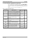
The T400 analyzer comes equipped with three analog outputs. The first two outputs (A1
& A2) carry analog signals that represent the currently measured O
3
output (see Section
5.4.1.2). The third output (A4) can be s
et by the user to carry the current signal level of
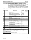
any one of several operational parameters (see Table 5-8).
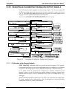
To access the
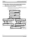
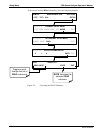
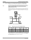
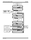
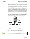
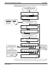
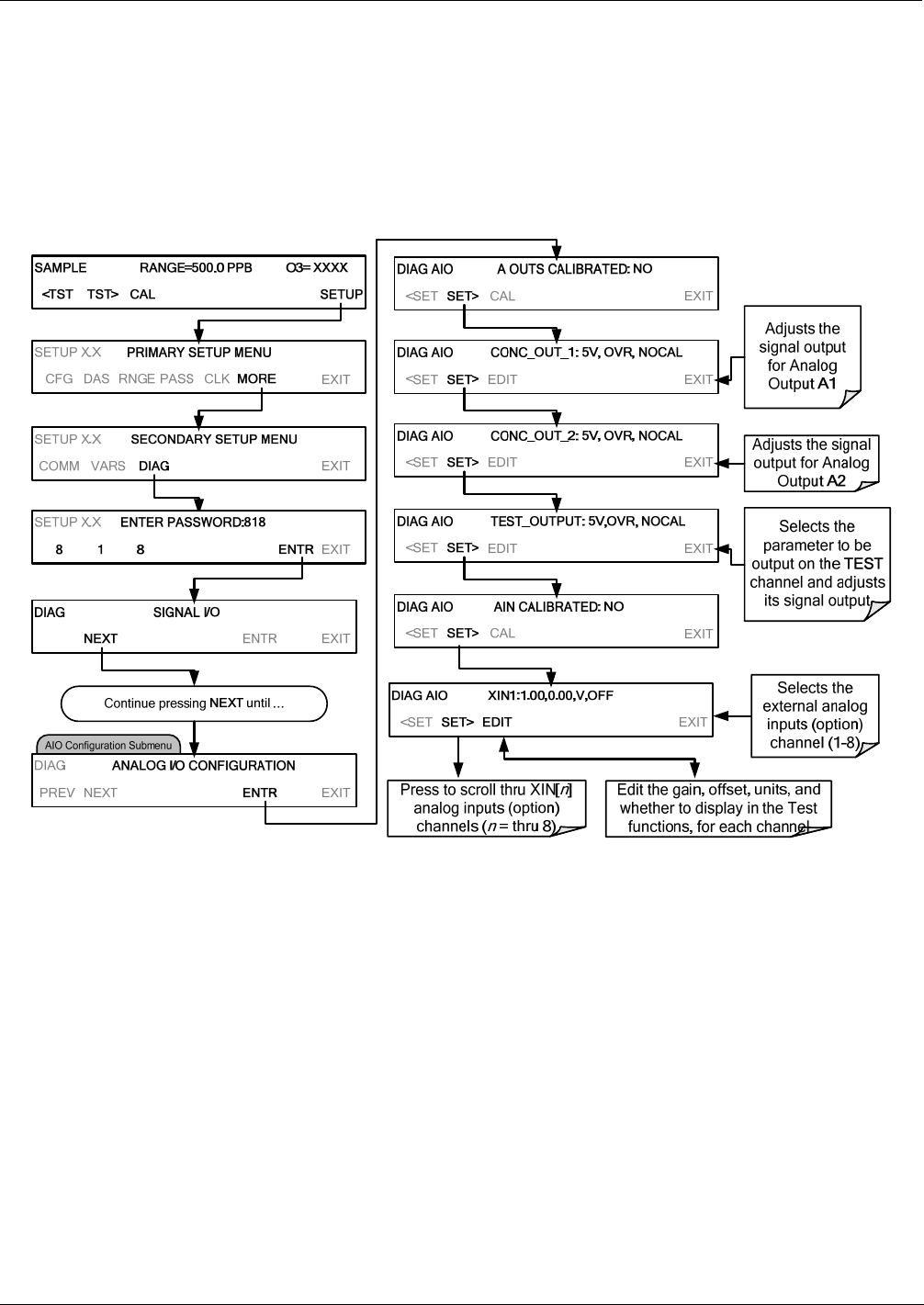
ANALOG I/O CONFIGURATION sub menu, press:
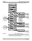
Figure 5-3: Accessing the Analog I/O Configuration Submenus
5.10.1.1. Calibration of the Analog Outputs
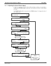
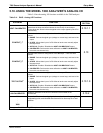
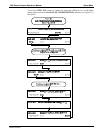
TEST CHANNEL calibration needs to be carried out on first startup of the analyzer
(performed in the factory as part of the configuration process) or whenever re-calibration
is required. The analog outputs can be calibrated automatically or adjusted manually.
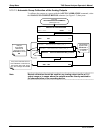
In its default mode, the instrument is configured for automatic calibration of all
channels, which is useful for clearing any analog calibration warnings associated with
channels that will not be used or connected to any input or recording device, e.g.,
datalogger.
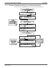
Manual calibration should be used for the 0.1V range or in cases where the outputs must
be closely matched to the characteristics of the recording device. Manual calibration
requires the AUTOCAL feature to be disabled.
06870C DCN6332


