


Teledyne API – Model T400 Photometric Ozone Analyzer Getting Started
59
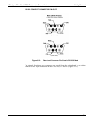
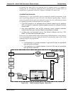
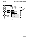
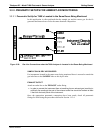
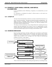
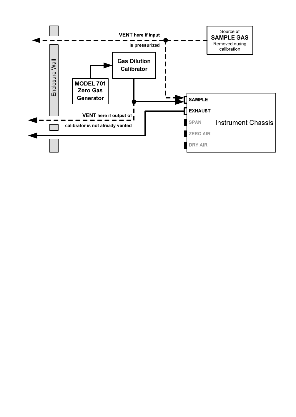
3.3.2.2. Pneumatic Setup for Basic Configuration
Figure 3-18: Gas Line Connections for the T400 Analyzer – Basic Configuration
For the Model T400 photometric ozone analyzer in its basic configuration (i.e. without
the optional internal zero air source or valves), attach the following pneumatic lines:
SAMPLE GAS SOURCE:
Attach a sample inlet line to the sample inlet fitting.
Sample Gas pressure must equal ambient atmospheric pressure (1.0 psig)
In applications where the sample gas is received from a pressurized manifold, a
vent must be placed on the sample gas line. This vent line must be:
At least 0.2m long
No more than 2m long
Vented outside the shelter or immediate area surrounding the instrument
CAL GAS & ZERO AIR SOURCES:
The source of calibration gas is also attached to the SAMPLE inlet, but only when a
calibration operation is actually being performed.
EXHAUST OUTLET:
Attach an exhaust line to the EXHAUST outlet fitting.
The exhaust line should be a maximum of 10 meters of ¼” PTEF tubing.
Once the appropriate pneumatic connections have been made, check all pneumatic
fittings for leaks using the procedures defined in Section 11.3.4.
06870C DCN6332