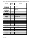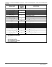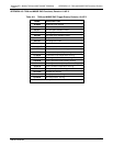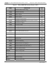
Teledyne API - Models T400 and 400E (04402F DCN6340) APPENDIX A-7: MODBUS Register Map
A-29
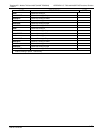
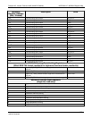
MODBUS
Register Address
(dec., 0-based)
Description Units
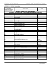
138
4
External analog input 2 slope eng unit /V
140
4
External analog input 2 offset eng unit
142
4
External analog input 3 value Volts
144
4
External analog input 3 slope eng unit /V
146
4
External analog input 3 offset eng unit
148
4
External analog input 4 value Volts
150
4
External analog input 4 slope eng unit /V
152
4
External analog input 4 offset eng unit
154
4
External analog input 5 value Volts
156
4
External analog input 5 slope eng unit /V
158
4
External analog input 5 offset eng unit
160
4
External analog input 6 value Volts
162
4
External analog input 6 slope eng unit /V
164
4
External analog input 6 offset eng unit
166
4
External analog input 7 value Volts
168
4
External analog input 7 slope eng unit /V
170
4
External analog input 7 offset eng unit
172
4
External analog input 8 value Volts
174
4
External analog input 8 slope eng unit /V
176
4
External analog input 8 offset eng unit
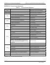
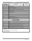
MODBUS Floating Point Holding Registers
(32-bit IEEE 754 format; read/write in high-word, low-word order; read/write)
0
Maps to O3_TARG_ZERO1 variable; target zero concentration for
range #1
Conc. units
2 Maps to O3_SPAN1 variable; target span concentration for range #1 Conc. units
4
Maps to O3_TARG_ZERO2 variable; target zero concentration for
range #2
Conc. units
6 Maps to O3_SPAN2 variable; target span concentration for range #2 Conc. units
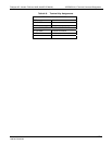
MODBUS Discrete Input Registers
(single-bit; read-only)
0 O
3
generator reference detector warning
1 O
3
generator lamp intensity warning
2 O
3
generator lamp temperature warning
3 O
3
scrubber temperature warning
4 Photometer reference warning
5 Photometer lamp stability warning
6 Photometer lamp temperature warning
7 Box temperature warning
8 Sample temperature warning
9 Sample flow warning
06870C DCN6332


