


5. Base Specifications Parameters
48
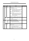
# Items Details
Setting range (unit)
1226 aux10
(bit6)
Setup and
display unit
Specify the unit to be used as the setup/display unit or
handle feed unit, the command unit or internal unit.
0: Internal unit
1: Unit specified by command
(Note 1) This parameter is valid only in initial millimeter
mode (0 is set in "#1041 I_inch"). The
internal unit is always used in initial inch
mode (1 is set in "#1041 I_inch").
(Note 2) This parameter is validated immediately after
it is set.
(Note 3) If addition setting is performed for tool and
workpiece offset data with the command unit
being inch and internal unit being mm, an
error may be generated.
Related parameter: #1152 I_G20 (Initial command
unit)
0/1
aux10
(bit7)
Shorten JOG
stop time
Specify whether to shorten the JOG stop time.
0: Do not shorten the JOG stop time. (Same as
before)
1: Shorten the JOG stop time.
0/1
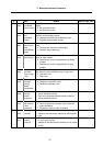
1227 aux11
(bit0)
Select PLC
signal or
spindle
feedrate
attained
Set up this option when disabling the cutting start
interlock by spindle feedrate attained.
0: Cutting start interlock by PLC signal
1: Cutting start interlock by spindle feedrate attained
0/1
aux11
(bit1)
Select H or D
code
Set up this option to validate the data that is set up on
the tool life management screen when issuing the H99
or D99 command.
0: The H and D codes validate the data that is set up
on the management setup screen.
1: Validates the data that is set up on the manage-
ment setup screen when issuing the H99 or D99
command.
0/1