


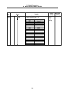
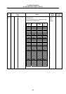
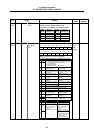

8. Spindle Parameters
8.3 MDS-B-SP/SPH, MDS-C1-SP/SPH
216
No. Items Details
Setting
range
Standard
setting
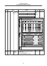
3296
(PR)
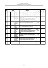
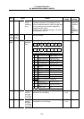
SP096 EGAR Encoder gear
ratio
Set the gear ratio between the spindle end
and the encoder end (except for the
motor-built-in encoder) as indicated below.
Setting
value
Gear ratio
(acceleration)
–1 1 : 2
–2 1 : 4
–3 1 : 3
Setting
value
Gear ratio
(deceleration)
0 1 : 1
1 1 : 1/2
2 1 : 1/4
3 1 : 1/8
4 1 : 1/16
–3 to 4 0
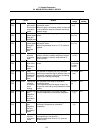
3297
(PR)
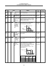
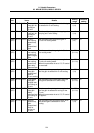
SP097 SPECO Orientation
specifica-
tion
Set the orientation specifications in bit units.
0000 to
FFFF
HEX
setting
0000
F E D C B A 9 8
ostp orze ksft gchg ips2 zdir
7 6 5 4 3 2 1 0
vg8x mdir fdir osc1 pyfx dmin odi2 odi1
(Note) Always set "0" for the empty bits.
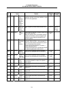
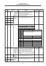
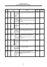
bit Name Meaning when set to 0 Meaning when set to 1
0 odi1
1
odi2
Orientation rotation direction
00: Previous (the direction in which the motor has
so far rotated under speed control)
01: Forward rotation
10: Backward rotation
11: Prohibited (Same as setting value = 10)
2
dmin Orientation in-position
advance invalid
Orientation in-position
advance valid
3
pyfx Excitation min. (50%)
during orientation servo
lock invalid
Excitation min. (50%)
during orientation servo
lock valid
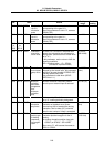
4
osc1 Indexing speed clamp
invalid
Indexing speed clamp
valid
5
fdir Encoder detector
polarity: +
Encoder detector
polarity: –
6
mdir Magnetic sensor
polarity: +
Magnetic sensor
polarity: –
7
vg8x Speed gain *1/8 during
torque limit valid
Speed gain *1/8 during
torque limit invalid
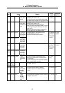
8
9
zdir This is used by Mitsubishi.
Set to "0" unless particularly designated.
A ips2 2nd in-position invalid 2nd in-position valid
B
C
gchg Gain changeover during
orientation invalid
Gain changeover during
orientation valid
D
ksft Orientation virtual target
shift invalid
Orientation virtual target
shift valid
Eorze
Fostp
This is used by Mitsubishi.
Set to "0" unless particularly designated.
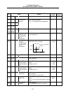
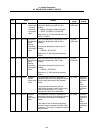
In-position advance (bit 2)
0 (invalid) 1 (valid)
0
(Invalid)
In-position signal in OINP
width=1
Control output 4/ bit 4=1
Second in-position
signal=0
Control output 4/ bit F=0
Second in-position
1
(Valid)
In-position signal in OINP
width=1
Control output 4/ bit 4=1
Second in-position
signal=0
Control output 4/ bit F=1
In-position signal in DINP
width=1
Control output 4/ bit 4=1
Second in-position signal
in OINP width = 0
Control output 4/ bit F=1