


Tests and Error Messages
68 Chapter 7 Tests and Error Messages
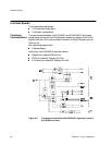
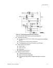
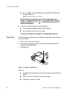
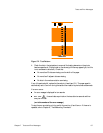
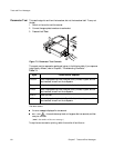
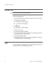
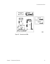
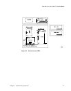
Parameter Test This tests the signal to and from the transducer, but not the transducer itself. To carry out
the test:
1. Switch on the monitor and the recorder.
2. Connect the appropriate transducer to each socket.
3. Press and hold
Test.
Figure 7-3 Parameter Test Controls
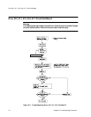
The correct monitor response for each signal is given in the following table. If your response
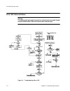
is significantly different, refer to Chapter 8, “Troubleshooting Flowcharts.”.
If an error occurs:
An error message is displayed for ten seconds.
Err xxx , time and date are printed on the paper after ten seconds, and then
every ten minutes.
(xxx is the number of the error message.)
To stop the error annotation printing, switch the monitor off and then on.
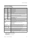
Table 7-1
Signal Correct Monitor Response
US/US1 190 is displayed and printed, the Signal Quality Indicator is green, and the
fetal heartbeat is heard from the loudspeaker.
Toco A signal alternating between
10 and 60 is displayed and printed.
DECG
200 is displayed and printed, the Signal Quality Indicator is green, and the
fetal heartbeat is heard from the loudspeaker.
MECG
120 is printed.
US2
170 is displayed and printed, the Signal Quality Indicator is green, and the
fetal heartbeat is heard from the loudspeaker.