


Telemetry System
Chapter 10 Peripherals 115
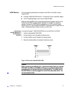
Telemetry System
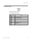
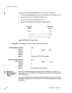
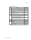
The following table lists the signals at each pin. There is no external parameter input, no
HR2 input and no US envelope input.
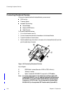
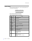
Figure 10-8Telemetry System Pin Connections
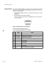
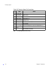
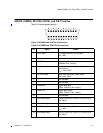
Table 10-5 Telemetry System Pin Connections
Pin Signal Details
1 HR2 Input Not connected (HR-LF2).
2 -12V Output 20mA maximum.
3 +5V Output 20mA maximum.
4 +12V Output 20mA maximum.
5 S1 Input Telemetry On (L).
6 S2 Input
7 S3 Input DECG inop (L). (M1353A only.)
8 S4 Input DECG Mode (L). (M1353A only.)
9 S5 Input AECG Mode (L). Not currently used.
10 S6 Input US Mode (L).
11 S7 Input
12 S8 Input IUP Mode (L). (M1353A only.)
13 S9 Input Toco External Mode (L).
14 HR1 Input HR-LF.
US range: -3.5V to +3.5V.
DECG range: -6V to +6V.
R
i
: >82kΩ.
15 Toco Input Toco dc.
Voltage range: -3V to +2V.
Sensitivity: -1V full scale (-1V=+100 units).
R
i
: >82kΩ.