


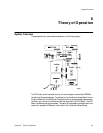
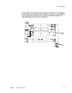
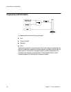
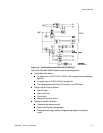


CPU Board (M1353-66503 and M1353-66513)
Chapter 6 Theory of Operation 57
CMOS RAM memory, backed by a battery to store short time device settings etc.
A non-volatile EEPROM memory for permanent device and user settings.
A real-time clock, battery-backed and power-fail protected. The processor has
access to all clock registers.
The multiplexer ASIC contains a watchdog function which monitors the
operation of the microprocessor and restarts the system if it is not served at a
constant rate.
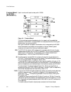
AD/DA Section:
After system startup, the CPU starts the A/D control chip, which divides the
signal from the clock circuit and generates an interrupt every 2.5 ms.
The 68000 on the CPU Board then programs the multiplexer to select the analog
channels for A/D conversion: the analog/digital conversion of up to eight
channels is done by the multiplexer without further intervention by the CPU. A/
D conversion is by successive approximation. After the next interrupt, the CPU
reads the results stored in registers within the multiplexer. The multiplexer also
receives values from the CPU for audio output.
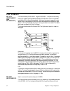
All LF signals are multiplexed, sampled at either 1600 or 800Hz, and A/D
converted with 12-bit resolution.
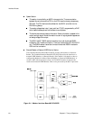
Digital Signal Processing Section:
Signal processor and RAM.
DMA logic.
DSP software rebooted when the US2 channel socket is connected/disconnected.
Bus Control Section:
Address and data bus control chips.
Board select logic to access all system boards.
DMA circuits to allow DMA access via the system bus to the Combined Interface.
A crystal quartz oscillator and related circuitry provide several local and bus clock
frequencies.
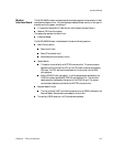
Service Interface: An RS232 serial interface is provided for use during production and
service. Connection is via a stereo phone jack on the front panel.
Serial interface for option and software upgrades.
Settings and configuration via an external computer.