


Interface Boards
62 Chapter 6 Theory of Operation
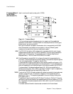
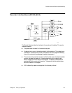
System Section:
This section is controlled by an 80C51 microcontroller. The communication
between this controller and the CPU on the CPU board is done by dumps every
250 msec. The CPU also boots the software for the 80C51 controller into the
ROM during startup.
The analog voltages heart rate 1, heart rate 2 and TOCO are generated by a DAC
which feeds three sample and hold buffers via a multiplexer.
The latch stores mode and status information. Status information is passed to the
output as a logic signal. Mode information is a sum of logic signals and appears as
an analog voltage at the output.
The 80C51 UART, RS422 receiver/transmitter form a bi-directional RS422
interface for OB TraceVue connection. Combined Interface Board M1353-66531E
only: The RS232 receiver transmitter forms a bi-directional RS232 interface for
OB
TraceVue connection.
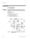
Barcode Reader or Maternal NIBP Monitor Section:
The Combined Interface Board M1353-69531 provides the interface to a Barcode
Reader. The Combined Interface Board M1353-69531E provides the interface to a
maternal NIBP Monitor or a Barcode Reader. (See Chapter 10 for details on how to
configure the Monitor for either a Barcode Reader or a maternal NIBP Monitor). A
second UART with driver/receiver form a
±12V RS232 interface for the barcode
reader or the maternal NIBP Monitor. Data is also processed by the 80C51 processor.
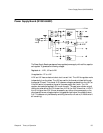
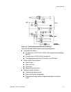
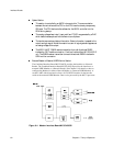
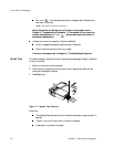
Figure 6-4 Modem Interface Board M1353-69532