


Connecting Peripheral Devices
Appendix A Modem Interface Module 157
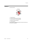
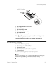
Barcode Reader
Interface
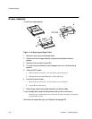
Once the barcode reader is installed, check that it is operating correctly. See the User’s
Guide for your monitor for instructions on how to use the barcode reader.
1. Use the barcode reader to scan Test Barcode 1 and then Test Barcode 2 from the
barcode sheet.
2. Check that TEST OK5 is printed on the paper. If it is not, switch the monitor off and
on, and repeat the test. If it is still not printed, connect a new barcode reader.
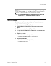
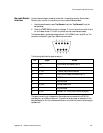
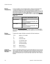
The barcode reader interface has voltage levels of
±12V, 9600bd, max.1 byte/20 ms. The
connector is a female D-type, 9-pin subminiature connector.
The following table lists the signal at each pin:
The supply current to pin 9 depends on the modem card connected to the PCMCIA
interface port; up to 300mA maximum. To ensure the correct power-on sequence for the
Barcode Reader, pin 9 of the interface is switched on only when the monitor's power supply
has stabilized.
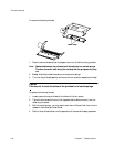
Pin Signal Details
1 CD Carrier detect (connected to pin 4)
2 I: RxD Receive data from external devices
3 I: TxD Transmit data to external devices
4 DTR Data Terminal Ready (connected to pin 1)
5 Gnd RS232 Gnd
6 - Not connected
7 B_Gnd Barcode Reader Gnd
8 - Not connected
9 B_Vcc Barcode: +5V, 10mA (idle) to 35mA (configure)