


Booting and Self Tests
50 Chapter 6 Theory of Operation
Booting and Self Tests
The monitor carries out a basic test every time it is switched on, and then at periodic
intervals while it is on. There are two types of test:
Programs that check the hardware on each board.
Programs that carry out checksums on the individual portions of code that are loaded
from the Flash EEPROMs.
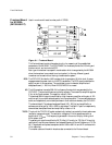
When the monitor is switched on, the initial reset generated by the power supply is fed to
the CPU Board, where it is latched and passed to the other boards. Each board latches the
reset to light its error LED. The LED can only be switched off by the CPU Board de-
latching it.
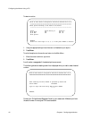
All error LEDs are on at the start of the tests. If a hardware error is detected on a board, its
error LED stays on and its error code is shown on the display. (The error code is the last
three digits of the board’s part number.) But note that if any element in the display chain is
not working, the errors may not be displayed. If a board passes its test, the LED goes out,
and the next board in the sequence is tested.
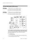
The Power Supply Board, Front End Board and Recorder Board have no processor and so
are tested by the CPU Board.
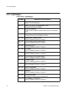
The boards are tested in the following sequence:
1. CPU Board.
2. Power Supply Board.
3. Front End Board.
4. Recorder Board.
5. Combined Interface Board (if one is fitted).
6. Modem Interface Board (if one is fitted).
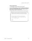
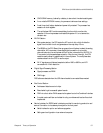
The processor on the CPU Board runs a self-test program from the Flash EEPROMs to test
certain functions of the CPU Board:
If the test fails, the red LED stays on and “Err 503'' is displayed.
If the test is successful, the red LED on the board goes out.
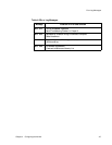
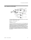
The current limits of the outputs of the Power Supply Board are then checked:
If any currents are out of limits, ``Err 502'' is displayed. Note that this does not
necessarily mean that the Power Supply Board is faulty (for example, a short on
another board could be drawing too much current).
If the test is successful, the red LED on the CPU Board is switched off.
All other boards are then tested. The red LEDs on the Front End Board and the
Recorder Board are lit for about 1 s, and then switched off when the test is successful.