


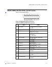
80235A (OBMS), M1370A (ODIS), and OB TraceVue
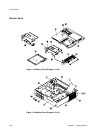
118 Chapter 10 Peripherals
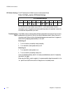
Key (L)\means Logic input/output is low (0 V).
(H)\means Logic input is high (5 V).
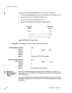
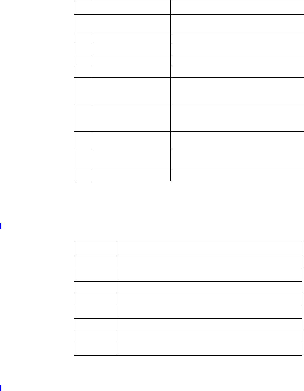
In the event of a paper-out or an HR-coincidence, an analog signal is applied to pin 21.
This lasts approximately 600 msec and is repeated every minute for as long as the condition
remains. The exact output voltages are shown in Table 10-7.
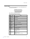
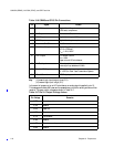
15 RS422 Output - Digital Serial Output.
1200 baud, complement.
16 0V Output Connected to Ground.
17 RS422 Input + Digital Serial Input: 1200 baud.
18 RS422 Input - Digital Serial Input: complement.
19 Instrument On/Off Not Connected.
20 Ext Marker Output Digital Signal Output.
0V: On (>250ms).
R
out
: 1.1kΩ, 100nF.
21 HR1 Output 1V/100bpm ±30mV.
R
out
: 100Ω.
Paper-out and HR-coincidence.
22 Ext Test Input When input is low, external test is on.
Internal pull-up resistance: 4.64k
Ω.
23 Monitor ID Output 2.0V regulated.
R
i
: 100Ω (for Fetal Trace Transmission System).
24 Chassis Ground RS232 signal ground.
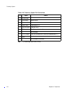
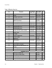
Table 10-7 Pin 21: Output Voltage Values
Pin Voltage Remarks
3.575 Normal operation.
3.725 Reserve.
3.875 Paper out.
4.025 Reserve.
4.175 Coincidence.
4.325 Reserve.
4.475 Coincidence and paper out.
4.625 Reserve.
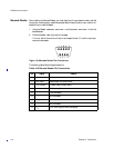
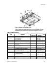
Table 10-6 OBMS and ODIS Pin Connections
Pin Signal Details