


Interface Boards
Chapter 6 Theory of Operation 63
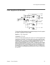
Modem
Interface Board
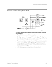
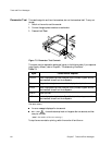
The M1353-66532 modem interface board allows the storage and the transmission of fetal
trace data via a telephone line. The interface board enables the fetal monitor to form part of
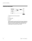
a remote monitoring system, consisting of:
A Transmitter (Series 50 A/IP Fetal Monitor with Modem Interface Option).
Receiver (OB TraceVue system).
The system also receives information from:
A Barcode Reader.
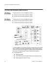
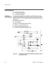
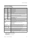
The M1353-66532 Modem Interface board includes the following sections:
Board Control section:
Board control latch
Board ID and status circuit
Bus buffers and clock recovery circuits
System Section:
This section is controlled by an M37702 microcontroller. The communication
between this controller and the CPU on the CPU board is done by dumps every
250 msec. The CPU also boots the software for this controller into the RAM
during startup.
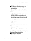
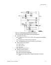
When a PCMCIA card is plugged in, it will be recognized and activated by the
PCMCIA interface, specified by PCMCIA card standard 2.01. The controller
deactivates this interface after the removal of the PCMCIA card. The modem
commands and data are controlled by the M37702 microcontroller.
Barcode Reader Circuits
The first controller UART and the driver/receiver form an RS232 interface for the
Barcode Reader. Barcode data is processed by the controller.
The auxiliary RS232 serial port (no Philips software available).