


Honeywell
MK XXII EGPWS Installation Manual
CAGE CODE: 97896 SCALE: NONE SIZE: A DWG NO: 060-4314-225 REV: C
SHEET
84
3.3.8 Category 8 – Radio Altitude Input Select
Category 8 defines the Radio Altitude and Decision Height interface.
3.3.8.1 Instructions
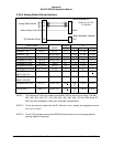
1. Using Appendix E Tables E 3, under Step/category 8 select Radio Altitude Type. Using table
E 3.1.8 and E 3.1.8-x select ID number for your Radio Altimeter and record that number on
Table E 3 under Ident No. for step 8. This number will be used during programming of the
configuration module.
2. Appendix E Tables E 3.1.8-x, where x is the Radio Altimeter Type number, define the
electrical interfaces required to support each Radio Altimeter. Using Table E 3.1.8-x
determine the wiring interconnects and record it on Appendix A Fig A1-1.
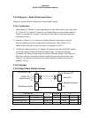
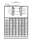
3. The Decision Height discrete (J1-33, Category 8) indicates to the MK XXII EGPWC whether
the aircraft is above or below the selected Decision Height. This discrete is typically
connected to the Decision Height output on the Radio Altimeter indicator. If the ‘Minimums-
Minimums’ callout is not wanted the Decision Height discrete should be left open. Using
Table E 3.1.8-x determine the wiring interconnects for Decision Height and record it on
Appendix A Fig A1-1.
3.3.8.2 Example
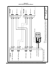
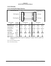
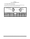
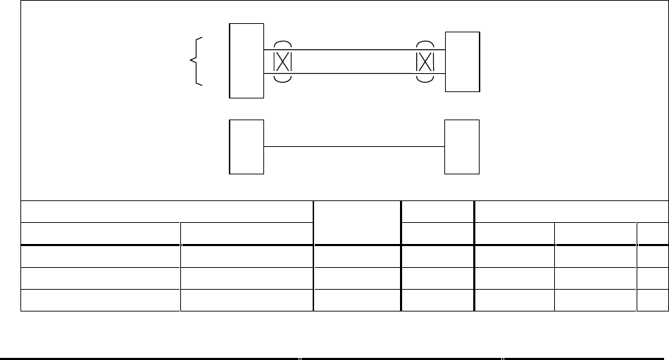
3.3.8.3 Digital Radio Altitude Interface
21
4
J2
Radio Altimeter R/T
A
B
EGPWS MK XXII
A
B
ARINC 429
Radio Altitude
ARINC 429
DH Discrete (Gnd)
33
Radio Altimeter Indicator
DH
J1
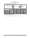
Vendor Model Indicator R/T
R/T Indicator SCALE DH A B
Collins RAC-870 ALI-55 ARINC 429 P1-V P1-2 P1-3
Honeywell ALA-52A ARINC 429 MP-B2 MP-B3
Honeywell KRA 405B KNI-415/416 ARINC 429 M B C