


Honeywell
MK XXII EGPWS Installation Manual
CAGE CODE: 97896 SCALE: NONE SIZE: A DWG NO: 060-4314-225 REV: C
SHEET
36
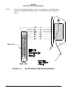
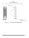
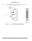
D. Position Slide Lock and Spring Clip onto connector.
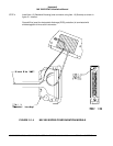
E. Install Backshell Housing onto connector. The Ground wire (used for ESD discharge) is terminated
with shielded pigtails inside the backshell to the P2 connector.
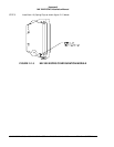
F. Organize and dress wire exiting from the backshell, route Configuration Module wires in a coil. Install
Cable Clamp, do not tighten Cable Clamp screws.
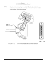
G. Secure the Configuration Module to the connector using screws provided. Tighten Cable Clamp
screws as required.
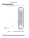
CONFIGURATION MODULE ASSEMBLY
REQUIRED: Two items as follows:
ITEM 1.0 Connector (P2) Positronic Ind. RD50F10JVLC-15 *
ITEM 2.0 Configuration Module Honeywell 700-1710-001
* This item may be available from Honeywell under Part No. (440-1233-001)
ITEM 1 DESCRIPTION:
Connector P2 (Positronic Ind. PN RD50F10JVLC-15) is a packaged kit consisting of the following parts:
1.1 Connector, 50 socket D-Sub Qty - 1
1.2 Contacts, size 20 crimp Qty - 50
1.3 Backshell housing Qty - 1
1.4 Backshell plate Qty - 1
1.5 Screws, Phillips CSK Qty - 2
1.6 Spring Clip Qty - 1
1.7 Slide Lock Qty - 1
1.8 Screws, Slotted Qty - 2
1.9 Cable Clamp Qty - 1