


Honeywell
MK XXII EGPWS Installation Manual
CAGE CODE: 97896 SCALE: NONE SIZE: A DWG NO: 060-4314-225 REV: C
SHEET
171
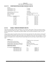
E 4.2.7.3 CONFIGURATION DEFINED SYNCHRO INPUTS
Quantity 3
Input Impedance: X leg
> 140 K
Ω
Input Impedance: Y leg
> 140 K
Ω
Input Impedance: Z leg
> 140 K
Ω
Maximum Reverse Fault Current
< 200
µ
amps
Input Voltage Range ±11.8 VAC
RMS
± 20% (leg to leg)
Reference Voltages
±
26 VAC
RMS
± 20%
Accuracy 2.5% linearity + 0.1% full scale offset
Pin Assignment (Signal Mnemonic):
#1 X leg
#1 Y leg
#1 Z leg
#2 X leg
#2 Y leg
#2 Z leg
#3 X leg
#3 Y leg
#3 Z leg
J1-5
J1-7
J1-6
J2-1
J2-2
J2-18
J2-19
J2-20
J2-3
(SYN_3X)
(SYN_3Y)
(SYN_3Z)
(SYN_4X)
(SYN_4Y)
(SYN_4Z)
(SYN_5X)
(SYN_5Y)
(SYN_5Z)
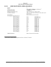
E 4.2.8 SIGNAL TIMING REFERENCE INPUTS
These inputs accept 400 Hz AC signals, and detect the “zero crossings” of these signals. These zero crossings are used to
time the conversion and input of AC signals. Absolute voltage level of these signals is not measured, but it must be within
the range specified below. Voltage below the specified minimum value may result in intermittent or “jittery” zero cross
detection.
Timing reference signals are required for input of most AC devices (not required for roll). These references can be brought
into the appropriate timing reference input, or the system can be configured to derive a reference from the signal. Timing
reference signals are specified for synchro inputs requiring a range greater than
±
80 degrees. Inputs requiring less (i.e., Roll
Attitude) are configured to derive a reference from the synchro input signal and do not require a separate reference voltage
input.
Quantity 2
Input Impedance
> 140K
Ω
each line to signal ground
Maximum Reverse Fault Current
< 120
µ
amps
A/C Input Signal Frequency Range
400 Hz,
±
10%
Maximum Input Voltage Swing (differential) 50V between input legs
Maximum Input Voltage Swing (ref. to Gnd) 50V from any leg to signal ground
Input Hardware Filtering None
Minimum Input Voltage
±
0.5 VAC
Pin Assignment (Signal Mnemonic):
26VAC Reference #1 H
26VAC Reference #1 C
26VAC Reference #2 H
26VAC Reference #2 C
J1-4
J1-24
J2-34
J2-35
(26REF_1H)
(26REF_1L)
(26REF_2H)
(26REF_2L)