


Honeywell
MK XXII EGPWS Installation Manual
CAGE CODE: 97896 SCALE: NONE SIZE: A DWG NO: 060-4314-225 REV: C
SHEET
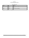
220
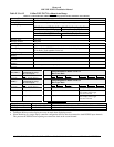
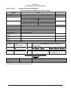
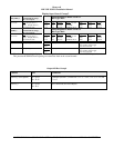
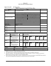
Display Input Control Group 2
CHANNEL
429_422RX_1
CONNECT TO:
WX-IND 429 out (range)
Bus 1 (Low Speed)
Fault Designation: DISPLAY BUS 1
Bus Type: Basic
A = J2-37
B = J2-36
Data
Mode (Display Word 1)
Range (Display Word 2)
Discrete Word (VP)
Reference
6.2.25
6.2.18
6.2.26
Label
270
271
273
Sig. Bits
Discrete
Discrete
Discrete
Range
Mode, Tilt, Gain
5-320NM
VP Mode, Bit 11
Signal Type
Basic
Basic
Basic
Resolution
N/A
N/A
N/A
Rate
100 ms
100 ms
100 ms
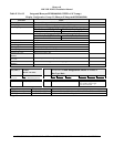
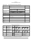
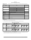
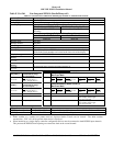
CHANNEL
429RX_3
CONNECT TO:
WX-IND 429 out (range)
Bus 2 (Low Speed)
Fault Designation: DISPLAY BUS 2
Bus Type: Basic
A = J2-41
B = J2-40
Data
Mode (Display Word 1)
Range (Display Word 2)
Discrete Word (VP)
Reference
6.2.25
6.2.18
6.2.26
Label
270
271
273
Sig. Bits
Discrete
Discrete
Discrete
Range
Mode, Tilt, Gain
5-320NM
VP Mode, Bit 11
Signal Type
Basic
Basic
Basic
Resolution
N/A
N/A
N/A
Rate
100 ms
100 ms
100 ms
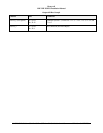
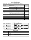
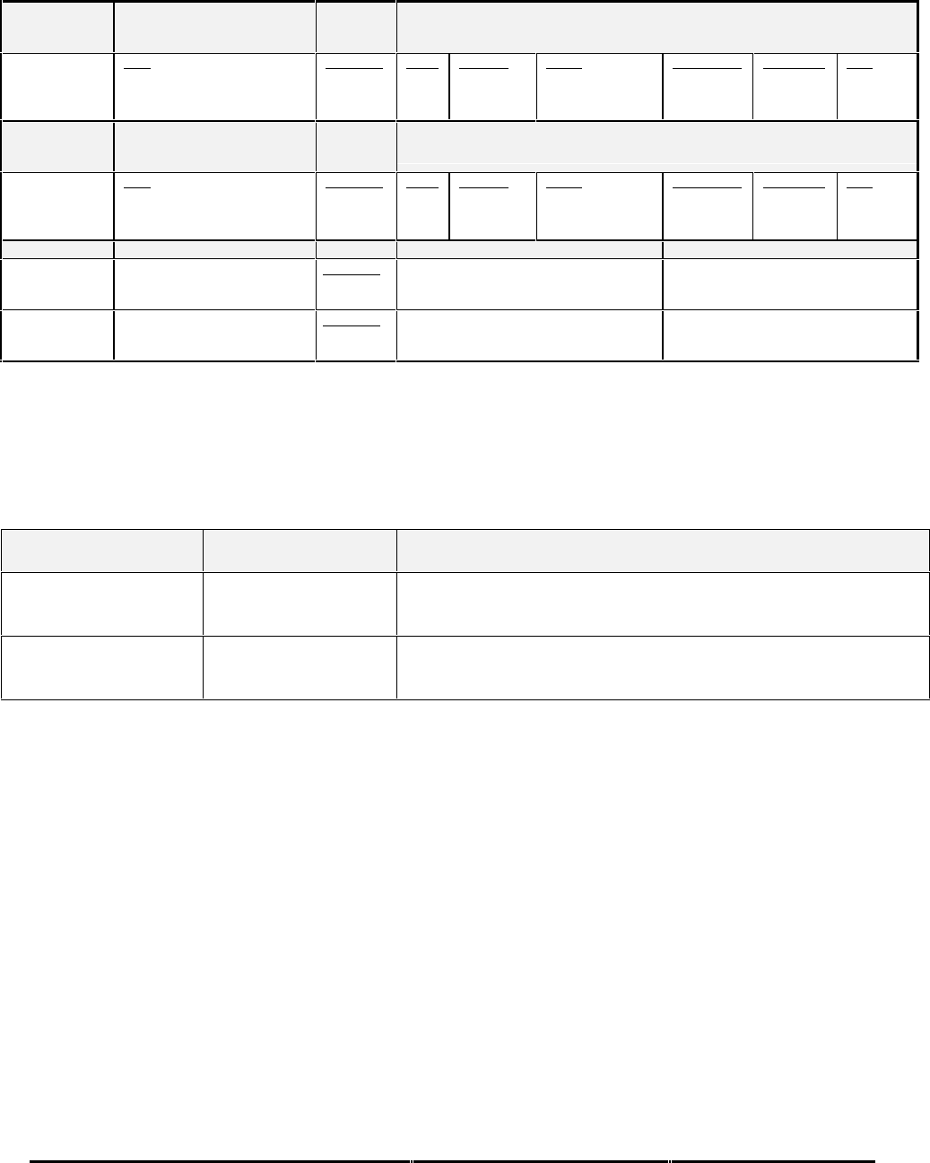
CONN PIN # REFERENCE NAME PIN FUNCTION Polarity/Configuration
J1-32 GND_DISC_12 Reference
4.2.7
6.6.18
Display Select Discrete #1 Type 1 (Momentary)
Gnd = Display Select Toggle
<not> Gnd = Normal
J1-31 GND_DISC_13 Reference
4.2.7
6.6.19
Display Select Discrete #2 Type 1 (Momentary)
Gnd = Display Select Toggle
<not> Gnd = Normal
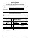
* When interfacing to a single display controller configuration the bus must be connected to both EGPWS input channels.
This prevents the EGPWS from reporting an external bus fault on the second channel.
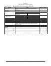
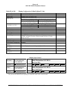
Output 429 Bus Group 0
Channel Pins Comments
429TX_1 (Low Speed) A = J2-43
B = J2-42
Transmits (Section 7) Label sets: 7.1.1.x, 7.1.2.x, 7.1.3.x, 7.1.4.x, and
7.1.6.x
1
429TX_2 A = J2-26
B = J2-9
No Connection (No Data Output)