


Honeywell
MK XXII EGPWS Installation Manual
CAGE CODE: 97896 SCALE: NONE SIZE: A DWG NO: 060-4314-225 REV: C
SHEET
167
E 4 ELECTRICAL INTERFACE
E 4.1 INTRODUCTION
The MK XXII EGPWS provides electrical interfaces for aircraft systems and to support maintenance functions. The
interfaces are made via the front panel aircraft interface connectors, front panel maintenance/test port and front panel LED’s.
A TNC coaxial connector is located on the front panel for internal GPS receivers in the 965-1590-0XX MK XXII EGPWC.
The following sections describe the types of electrical interfaces provided in the EGPWC. See Section E 5 for the specific
interface configuration capabilities of the MK XXII EGPWS.
E 4.2 SIGNAL INTERFACES
This section identifies and describes the number and characteristics of each interface type provided in the front aircraft
interface connectors. The aircraft interface connectors are defined as P1 (78 pins) and P2 (50 pins). Section E 6 identifies the
connector pin assignments. The signal mnemonic for each signal in Section E 6 is included in the following sections. All
synchro inputs are brought in as three or five wire devices. No two wire absolute AC signals are available. All analog inputs
provide broken wire detection on all input signal legs. Unless otherwise stated, the “Maximum reverse fault current” is
defined as the current resulting from an internal component failure, with the input signal at zero volts.
E 4.2.1 GROUNDS
CHASSIS GROUND
Used for redundant metal connection. This pin is internally connected to DC Ground (see section 0).
Pin Assignment (Signal Mnemonic): J1-42, J1-53 (GND)
DC GROUND
For discrete inputs and lamp driver outputs. These pins are also internally connected to Chassis Ground (see section 0).
Pin Assignment (Signal Mnemonic):
(same as +28 VDC Return) J1-41, J1-61 (PWR_L)
NOTE: All analog signals are differential input.
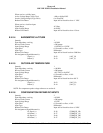
E 4.2.2 PRIMARY POWER INPUT
Nominal Input 28 VDC
Normal Voltage Range 22.0 to 30.3 VDC
Normal Surge Voltage Range 15 – 40VDC (30 msec)
Abnormal Voltage Range 20.5 to 32.2 VDC
Abnormal Surge Voltage Range 37.8 VDC (1sec); 46.3 VDC (100 msec)
Normal Frequency Range not applicable
Frequency Transients not applicable
Power Requirements 9 Watts - No Warnings
+7 Watts with warning voice over 8 Ω speaker
+3 Watts with Internal GPS (includes antenna power)
1
+49 Watts (typical) with heater blanket on
2
Recommended Power Control Device 3 Amp delayed action circuit breaker.
Pin Assignment (Signal Mnemonic):
+28 VDC Input
+28 VDC Return
J1-40, J1-60
J1-41, J1-61
(PWR_H
3
)
(PWR_L
3
)
1
Based on the Honeywell GPS Pxpress card specification and applies to 965-1590-0XX only.
2
The heater blanket turns on at temperatures ≤ -23° C and turns off at temperatures ≥ -20° C.