


Honeywell
MK XXII EGPWS Installation Manual
CAGE CODE: 97896 SCALE: NONE SIZE: A DWG NO: 060-4314-225 REV: C
SHEET
35
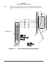
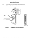
E. Slide the EGPWS unit in the mounting tray, and secure it using the Hold Down latch.
F. (After Continuity and Power check) Attach the cable harness to the front panel connectors and lock
connectors using the slide lock of the P1 & P2 connectors. The EGPWS should be wired according to
the interconnect diagrams in Section III, of this manual.
2.3.4 Configuration Module Location
The aircraft configuration is programmed into the EGPWS Configuration Module installed in the aircraft
wiring. The Configuration Module is identified as Honeywell part number 700-1710-001. The Configuration
Module is installed as one side of the P2 (50 pin) mating connector backshell and contains electrically
reprogrammable memory for configuration storage. The Configuration Module when installed is wired
directly to the appropriate pins in the P2 connector.
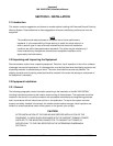
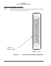
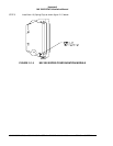
2.3.5 Configuration Module Installation
The purpose of this procedure is to give an assembly sequence for assembly of the Configuration Module
with the P2 connector and backshell.
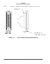
A. The P2 connector, Honeywell part number 440-1233-001, vendor part number RD50F1OJVLC-15,
when ordered comes with 50 contacts and a plastic backshell (hood).
B. The Configuration Module will replace the Backshell Plate. The Backshell Plate can be discarded.
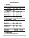
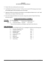
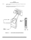
C. Wire the Configuration Module to the P2 connector using contacts provided with the connector. Wire
per the following wire list:
Wire Color P2 pin #
Violet P2-17
Blue P2-16
Orange P2-33
Wire Color P2 pin #
Black P2-50
White P2-49
Red P2-32