


Honeywell
MK XXII EGPWS Installation Manual
CAGE CODE: 97896 SCALE: NONE SIZE: A DWG NO: 060-4314-225 REV: C
SHEET
182
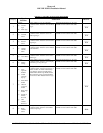
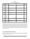
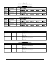
Step
(Category)
Signal
Selection
Instruction
Ident No.
9
Selects:
a) Glideslope
and/or
Localizer
Source
Using Table 5.3.9, and any sub-tables
contained within, locate the desired
Navigation signal type.
Record the Ident (ID No.) on the space
available on Ident column of this table.
_______
ID #
10
Selects:
a) Attitude
Source
Using Table 5.3.10, and any sub-tables
contained within, locate the desired Attitude
signal type.
Record the Ident (ID No.) on the space
available on Ident column of this table.
_______
ID #
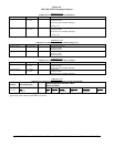
11
Selects:
a) Magnetic
Heading
Source
Using Table 5.3.11, and any sub-tables
contained within, locate the desired
Magnetic Heading signal type.
Record the Ident (ID No.) on the space
available on Ident column of this table.
_______
ID #
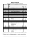
12
Selects: Using Table 5.3.12, no Windshear is
available for helicopter applications. Please
select ID 0.
Record the Ident (ID No.) on the space
available on Ident column of this table.
_______
ID #
13
Selects:
a) Input
Discrete
Functions
b) Output
Discrete
Functions
Using Table 5.3.13, and any sub-tables
contained within, locate the desired I / O
Discrete type.
Record the Ident (ID No.) on the space
available on Ident column of this table.
_______
ID #
14
Selects:
a) Audio
Output Level
Using Table 5.3.14, and any sub-tables
contained within, locate the desired Volume
type.
Record the Ident (ID No.) on the space
available on Ident column of this table.
_______
ID #
15
Selects:
a) Autorotation
Threshold
Using Table 5.3.15, locate the desired
Autorotation Threshold. This Category is
used on helicopters only.
Record the Ident (ID No.) on the space
available on Ident column of this table.
_______
ID #
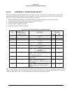
LIMITATIONS: The described use of the configuration module provides for maximum flexibility in selection of input
sensors and output behavior. Every attempt has been made to avoid conflicts arising between categories and to reflect the
known configurations of aircraft. However in the case of input sensors it should not be construed that all combinations are
valid configurations. There may be configurations not supported by the EGPWS software configuration building process
(which will cause the EGPWS to fail in an obvious manner). In general you can not have redundancy through the mixing of
analog and digital sources, however redundant digital signals on different buses are permissable. As it is not practical to
verify all possible sensor combinations, verification of particular sensor combinations is part of the installation certification
process. If you intend to implement a sensor configuration not currently identified in Section E 3, please contact Honeywell
or an authorized dealer/installer.
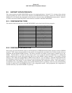
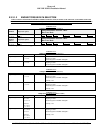
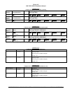
E 5.3 CONFIGURATION SELECTION TABLES
Configuration selection is defined by category (or group of functions or inputs). The Category number identifies the
subsection where the details are defined. For example Air Data, Category 2, is defined in Section E 5.3.2, and Position Input
Source, Category 3, is defined in Section E 5.3.3.
0