


Honeywell
MK XXII EGPWS Installation Manual
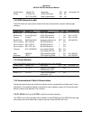
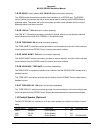
CAGE CODE: 97896 SCALE: NONE SIZE: A DWG NO: 060-4314-225 REV: C
SHEET
34
2.3.2 MK XXII Computer Loc ation
Care should be exercised to avoid mounting components near equipment operating with high pulse current
or high power outputs such as radar and satellite communications equipment. In general, the equipment
should be installed in a location convenient for operation, inspection, and maintenance, and in an area free
from excessive vibration, heat, and noise generating sources.
The MK XXII EGPWS has an internal heater blanket therefore they can be mounted outside the heated
area of the aircraft. The computers have been qualified for operation up to 50,000 feet and -55°C using the
heater blanket.
All mechanical installation drawings, connector assembly diagrams, interwiring diagrams, and connector
pin assignment tables referenced in this section are located at the end of Section II, of the manual.
Determine the mounting location for the system components following the guidelines below.
The length of cables from the EGPWS connectors to other system units is not generally critical because
unit interfaces are designed with high impedance inputs, low impedance outputs, and low noise
susceptibility characteristics. The exception is the wires from the EGPWS Configuration Module, which
was designed to be a part of the EGPWS connector backshell because of the requirement for short lead
length.
To allow for inspection or repair of the wiring of the connector assembly itself, sufficient lead length should
be left so that EGPWS may be moved several inches. A bend should be made in the harness to allow
water droplets that might form on the harness due to condensation, to drip off at the bend and not collect in
the connector.
Prior to installing any equipment, make a continuity check of all wires and cables associated with the
system. Then apply power and check for proper voltages at system connectors, and then remove power
before completing the installation.
2.3.3 MK XXII Computer Ins tallation
The MK XXII EGPWS installation will conform to standards designated by the customer, installing agency,
and existing conditions as to the unit location and type of installation. However, the following suggestions
will assure a more satisfactory performance from the equipment.
A. Plan a location on the aircraft so that the EGPWS is accessible for front panel maintenance controls.
Check to be sure that there is adequate space in the front of the computer for connectors and cabling.
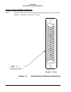
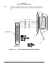
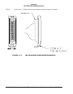
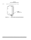
B. Refer to Figure 2-2 and 2-3 for outline dimensions of the computer and mounting tray.
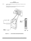
C. Mount the EGPWS mounting tray in the aircraft radio rack or other location using the four screw
mounting holes. Match drill the mounting holes using the Mounting Tray as a template.
D. Ensure that the mounting tray is electrically bonded (less than 10 milli-ohm to aircraft ground).