


Honeywell
MK XXII EGPWS Installation Manual
CAGE CODE: 97896 SCALE: NONE SIZE: A DWG NO: 060-4314-225 REV: C
SHEET
175
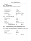
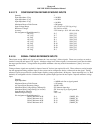
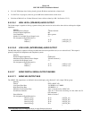
The Ground discretes are internally biased via a pull up resistor, and are externally pulled down to ground when active. The
characteristics of each Ground discrete input are as follows:
Ground Discrete Characteristics
Quantity 15
Active Voltage Range (Logic True) < +3 VDC
Inactive Voltage Range (Logic False)
> 100 K
Ω
(to ground) or > +3.5 VDC
Diode Isolation Each input is diode isolated to prevent current sinking
Input Impedance
> 10 K
Ω
Maximum Fault Current
< 100
µ
A (at +28 VDC input)
Pin Assignment (Signal Mnemonic): See specific discrete in Category 13 (GND_DISC_xx)
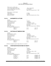
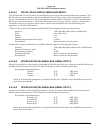
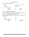
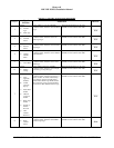
E 4.2.11 CONFIGURATION MODULE INTERFACE
System configuration is defined via a Configuration Module, which resides in the MKIV/VI/VIII/XXII EGPWS aircraft
wiring harness backshell. The EGPWS Configuration Module contains the aircraft interface and functionality definitions
specific to the installed aircraft. Refer to Section 5 for interface and functional definitions by category.
Electrical Characteristics Refer to the EGPWS Configuration Module specification
Data definition Refer to the EGPWS Configuration Module specification
Pin Assignment (Signal Mnemonic):
Clock
Master Data Out
Master Data In
Configuration Module Select
Configuration Module +5VDC
Configuration Module +5VDC Return
J2-32 (RED)
J2-50 (BLK)
J2-33 (ORN)
J2-49 (WHT)
J2-17 (VIO)
J2-16 (BLU)
(SPICLK)
(SPIMOSI)
(SPIMISO)
(SPISEL_CM#)
(SC_PWR)
(GND)
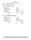
Output to Config Module Logic Low (nominal) Logic High (nominal)
EMK4/6/8/22 EMK4/6/8/22
Clock Out 0 V 5 V
Master Data Out 0 V 5 V
Config Module Select 0 V 5 V
INTERFACE OF EGPWS OUTPUTS TO CONFIGURATION MODULE
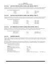
E 4.2.12 GPS ANTENNA INPUT
A GPS input connector is available on the front of the MK VI EGPWS (965-1186-0XX only), MK VIII EGPWS (965-1216-
0XX only), MK XXII EGPWS (965-1590-0XX only), and MK IV EGPWS (965-1686-0XX only).
Quantity 1
Cable Length/Allowed Signal Loss Not more than 8 dB, at 1575.42 MHz, for cable and
connector loss from antenna to unit.
Connector Type TNC
Low Level DC on RF Output +5 VDC ±5%, 50 mAmps maximum, Shield Ground.
Pin Assignment (Signal Mnemonic): GPS ANT (COAX)