


Honeywell
MK XXII EGPWS Installation Manual
CAGE CODE:
97896
SCALE: NONE SIZE: A DWG NO: 060-4314-225 REV: C SHEET
117
4.6.5 Accomplishment Instr uctions
Load the PCMCIA card data as described in paragraphs 4.6.5 A. or 4.6.5 B. below. Loading time
will be approximately 70 minutes.
A. Loading the PCMCIA Card Data with the Computer mounted in the Aircraft.
(1) Connect the Smart Cable (Honeywell PN 951-0386-001) to the EGPWC J3
connector.
(2) Ensure that the 28 VDC circuit breaker to the EGPWC is ON and that the
COMPUTER OK LED on the EGPWC front panel is on.
(3) Insert the PCMCIA card into the Smart Cable PCMCIA card slot.
NOTE: Precautionary notes on the PCMCIA card, regarding insertion and/or removal
while power is applied, should be ignored since the EGPWC automatically
handles the application and removal of PCMCIA card power.
(4) While the loading is in progress, the IN PROG LED on the Smart Card remains ON
and the COMPUTER OK LED on the EGPWC is OFF.
(5) When loading is complete the XFER COMP LED on the Smart Card turns ON.
(6) Remove the PCMCIA card from the Smart Card slot.
(7) After approximately 15 seconds the COMPUTER OK LED comes ON to indicate that
the contents of the PCMCIA card were successfully transferred.
(8) Remove the Smart Card connector from the EGPWC front panel J3 connector.
(9) To perform the verification of the Terrain Database version, go to paragraph 4.6.6
below.
B. Loading the PCMCIA Card Data with the Computer removed from aircraft
(1) Locate a 28 VDC Power Supply with a minimum supply current of 2 amps.
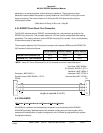
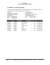
(2) With the Power Supply turned OFF, connect the Power Supply to the J1 connector of
the EGPWC as follows:
J1 connector Pin Pin Nomenclature
J1-40, J1-60 28 VDC (+)
J1-41, J1-61 28 VDC (-)
J1-42, J1-53 Chassis GND