


Honeywell
MK XXII EGPWS Installation Manual
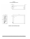
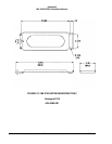
CAGE CODE: 97896 SCALE: NONE SIZE: A DWG NO: 060-4314-225 REV: C
SHEET
57
SECTION III – SYSTEM PLANNING
3.1 Introduction
This section provides information for selecting features and wiring the electrical interfaces of the
MK XXII EGPWS. Sample wiring diagrams for the most commonly used MK XXII EGPWS
configurations are provided in Appendix B. Appendix E Section E 3 groups features (functions)
into sets called Categories. This document follows the Category structure of the Appendix E . It
provides descriptions of the features and instructions for selecting features and for determining
the correct wiring.
1. Make a copy of Appendix E Table E 3. Use this table along with Appendix A Fig A-1.1, A1.2,
and A1.3 to record feature selection and determine the wiring interface.
3.2 System Wiring/ Electr ical Interfaces
System wiring is broken down into the following main components:
- Electrical Interfaces (power and ground)
- GPS Antenna
- Analog and Digital Inputs
- Discrete Inputs
- Serial Outputs
- Audio Outputs
- Discrete Outputs
- Configuration Module
Many of these inputs and outputs will be defined as the Categories are selected for Configuration
Module programming. Appendix E Table E 4 shows the typical usage for each pin, on the Left
(J1), Right (J2) and Upper (J3) connectors.
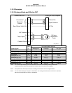
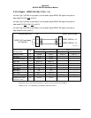
3.2.1 Primary Power Input
The MK XXII EGPWC requires a primary power input (28 VDC input power) and ground. The
Primary power should be connected as follows.
Pin Signal
J1-40, J1-60 +28 VDC Input
J1-41, J1-61 +28 VDC Return
Recommended EGPWC Power Control Device: 3 Amp Delayed Action Circuit Breaker
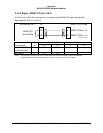
3.2.2 Chassis Ground
Chassis ground provides a redundant metal connection and should not be used as a normal
current carrying conductor. Chassis ground should be connected as follows:
Pin Signal
J1-42, J1-53 GND