


Honeywell
MK XXII EGPWS Installation Manual
CAGE CODE: 97896 SCALE: NONE SIZE: A DWG NO: 060-4314-225 REV: C
SHEET
180
E 5 AIRCRAFT APPLICATION DATA
This section describes the MK XXII EGPWS interfaces for aircraft applications. Section E 5.1 is a listing of the selection
categories defining the various aircraft sensor interfaces and EGPWS functional options. Section E 5.2 describes how the
Category ID’s are selected and programmed for the interface to aircraft sensors and EGPWS functional options. Section E
5.3 and its sub-sections define the specific aircraft interfaces available for the MK XXII EGPWS.
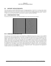
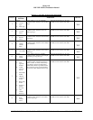
E 5.1 CONFIGURATION TYPES
The selection of the basic interfaces to the MK XXII EGPWS can be found in the following categories:
Category 1 Aircraft / Mode Type Select
Category 2 Air Data Input Select
Category 3 Position Input Select
Category 4 Altitude Callous
Category 5 Audio Menu Select
Category 6 Terrain Display Select
Category 7 Options 1 Select
Category 8 Radio Altitude Input Select
Category 9 Navigation Input Select
Category 10 Attitude Input Select
Category 11 Heading Input Select
Category 12 Windshear Input Select
Category 13 I / O Discretes Select
Category 14 Audio Output Level
Category 15 Autorotation Threshold
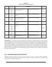
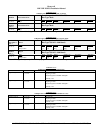
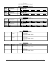
E 5.2 CONFIGURATION SELECTION
Each category provides information relative to aircraft interfaces or EGPWS functional options required or used for EGPWS
operation. Each category must be defined for the specific aircraft application according to the available aircraft sensors or
equipment and the intended EGPWS function. The choices provided are available in each category identified by an “ID”
number. The ID number is selected for each category and is used to load the selected configuration in a configuration
module installed in the aircraft wiring (physically part of one of the EGPWC mating connectors). For example, selecting
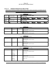
Category 2, ID 1 defines the Air Data Input as ARINC 429 per Table E 3.1.2-1 in Category 2. With this ID programmed into
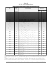
the configuration module the EGPWC will look for and use the interface defined for this ID. Table E 3 can be used to record
the selected ID for each category for later reference when programming the configuration module. This programming is
accomplished using a programming software tool available from Honeywell or generating a data text string and transferring
this data (in either case) via the EGPWC RS-232C to the configuration module. Once programmed, the configuration is
available and read by any installed EGPWC on power up.