


Honeywell
MK XXII EGPWS Installation Manual
CAGE CODE: 97896 SCALE: NONE SIZE: A DWG NO: 060-4314-225 REV: C
SHEET
73
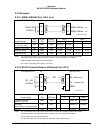
3.3.6.3 Terrain Display Configuration Group
This option provides the ability to specify the type of Terrain Display compatible with the aircraft
configuration. A definition of each of the entries in the Display Configuration Group tables is
provided in the table below.
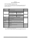
Function Value Reference section
Display Type
Display manufacturer, model, etc.
Sweep Type
The type of sweep used for terrain data (fan, standard, etc.)
Auto Pop Up Category 7, Options Select Group #1
TA&D Alternate Pop Up: False TA&D Alternate Pop Up: True
The TA&D Alternate Pop Up is set to
False or True in Category 7. If False,
Pop Up behavior for the terrain
display is described here.
The TA&D Alternate Pop Up is set to
False or True in Category 7. If True,
Pop Up behavior for the terrain
display is described here.
Peaks Mode Category 7, Options Select Group #1
See Note 1 Peaks Enable: False Peaks Enable: True
Peaks Enable is set to False or True
in Category 7. The effect of setting it
to False is described here.
Peaks Enable is set to False or True
in Category 7. The effect of setting it
to True is described here.
Manual select
Describes if/when terrain display(s) can be manually selected
Manual deselect
Describes if/when terrain display(s) can be manually deselected
Auto Range
Defines if the display data is automatically scaled and, if so, the scale used
(such as 10 nautical miles)
Moving Marker
Indicates whether or not a moving marker is provided
Overlay Page
Describes where “TERR” and Peaks Elevations overlays will be located on the
display screen.
Display Priority
Indicates the priority for displaying terrain data. For example:
Standard (PWS Warn, Terrain Warn, PWS Caution, Terrain Caution)
Searchlights
Display bus type
Defines the display bus type ‘KC Picture Bus’ (ASPB), ‘Honeywell Picture Bus’
or ‘ARINC 453’.
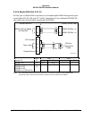
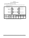
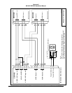
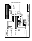
CHANNEL
TX453-1
CONNECT TO:
A = J1-58
B = J1-59
Indicates the correct connection for these pins
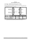
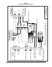
CHANNEL
TX453-2
CONNECT TO:
A = J1-56
B = J1-57
Indicates the correct connection for these pins
Notes: 1 Peaks Mode “(Not Available)” or “(Elevations via overlay)” shown here. Peaks mode “Not Available” means
that this display type cannot display Peaks Mode.
Table 0-1 Definition of Display Configuration Group Tables (Appendix E Section 5.3.6)