Honeywell
MK XXII EGPWS Installation Manual
CAGE CODE: 97896 SCALE: NONE SIZE: A DWG NO: 060-4314-225 REV: C
SHEET
178
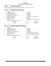
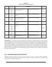
E 4.2.17.2 ARINC 453 OUTPUT BUS
Quantity 2
Format 1600 bit Manchester BI-phase per ARINC 708A
Data Rate 1 Mb per second
Word/Frame Structure Refer to Section 7.2
Data definition Refer to Section 7.2
Pin Assignment (Signal Mnemonic):
Bus #1 (A leg)
Bus #1 (B leg)
Bus #2 (A leg)
Bus #2 (B leg)
J1-58
J1-59
J1-56
J1-57
(KCPB_1A)
(KCPB_1B)
(KCPB_2A)
(KCPB_2B)
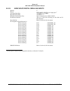
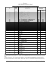
E 4.2.18 FRONT PANEL TEST INTERFACE
The MK IV, VI, VIII and XXII EGPWS provides a 15 pin (double density, D-Sub) test connector on the front panel, which
provides interfaces for various test and maintenance functions. This connector provides the following interfaces.
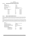
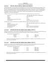
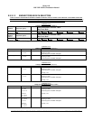
E 4.2.18.1 RS-232 MAINTENANCE PORT (SERIAL PORT 4)
One port is provided which meets the characteristics specified in RS232C. This bus can be used to read internal data from
the MK IV, VI, VIII and XXII EGPWS for both bench, and aircraft testing or transmitting configuration data for selected
EGPWS interfaces and options.
Baud Rate 19,200
Parity None
Data bits 8
Stop bits 1
Maximum Recommended Cable Length 15 meters
Pin Assignment (Signal Mnemonic):
Transmit
Receive
Common
J3-4
J3-3
J3-1
(RS232TXD_MON)
(RS232RXD_MON)
(GND)


