


Honeywell
MK XXII EGPWS Installation Manual
CAGE CODE: 97896 SCALE: NONE SIZE: A DWG NO: 060-4314-225 REV: C
SHEET
236
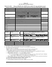
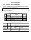
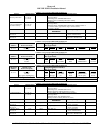
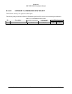
E 5.3.9 CATEGORY 9, NAVIGATION INPUT SELECT
The following table provides identification of the Navigation type. The entry in the Navigation Type corresponds to a table
that provides detailed information on the configuration. For example, the details for Navigation Type #1 are found in Table
0-1. In this category, only the following signals are defined:
•
Glideslope source selection.
•
Localizer source selection. (optional for digital only)
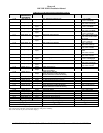
TABLE E 3.1.9: NAVIGATION INPUT SELECT FOR EGPWS MKXXII
I
D
Navigation
Inputs Select
Description Effectivity
(Table E 3.1.9-
x)
App. Cfg.
0 0 Analog Glideslope (ARINC 547) with +28V
Validity Flag
-001 -001
1 1 Analog Glideslope (ARINC 547) with Low Level
Validity
-001 -001
2 2 Digital Glideslope (ARINC 429) -001 -001
3 3 Digital Glideslope and Localizer (ARINC 429) -001 -001
4 4 Digital KN40 Glideslope and Localizer (ARINC
429)
-003 -003
5 5 Analog Glideslope/Localizer (ARINC 547) with
+28V Validity Flags
-008 -008
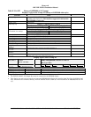
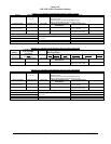
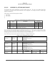
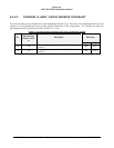
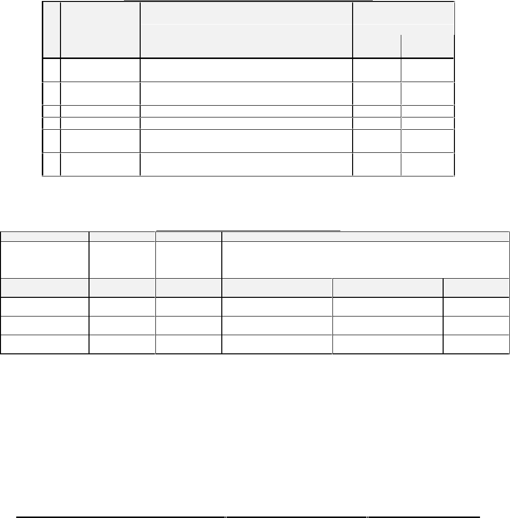
TABLE E 3.1.9-0: NAVIGATION INPUTS SELECT 0
SIGNAL CONNECTION SUMMARY DATA
Glideslope Deviation
(+) = J1-65
(-) = J1-46
Format: ARINC 547 with Validity Flag & ILS Select
Input Type: Basic
Fault Designation: GLIDESLOPE FAULT
Validity: Glideslope Validity Discrete #1 (+28V)
PIN FUNCTION
CONNECTION PIN TYPE
CHANNEL DESIGNATION
REFERENCE
Polarity/Configuration
Glideslope Validity
Discrete #1
J1-11 Input 28V_DISC_06 >+17V = Valid
< +4.4V = Not Valid
+28V ILS Tuned
Discrete #1
J1-39 Input 28V_DISC_01 >+17V = ILS Tuned
< +4.4V = ILS Not Tuned
GND ILS Tuned
Discrete #1
J1-20 Input GND_DISC_01 Gnd = ILS Tuned
<not> Gnd = ILS Not Tuned