


Honeywell
MK XXII EGPWS Installation Manual
CAGE CODE: 97896 SCALE: NONE SIZE: A DWG NO: 060-4314-225 REV: C
SHEET
168
3
Note that this is not a floating input. +28 VDC must be applied to both PWR_H and +28 VDC Return to both
PWR_L inputs.
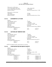
E 4.2.3 DC ANALOG INPUTS
Unless otherwise specified, Input Signal accuracy is1% linearity +0.1% full scale offset.
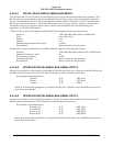
E 4.2.3.1 RADIO ALTITUDE
Quantity 1
Input Impedance, each leg
> 83 K
Ω
Maximum Reverse Fault Current
< 200
µ
amps
Signal Range 0 to 2500 feet
Input Voltage Range (V
RA
)
37.7V
≥
V
RA
≥
-2.5V
Conversion Range (V
c
)
29.7V
≥
V
c
≥
-0.4V
Input Filter
0.1 Second Low Pass,
±
10%
Broken Wire Detect Input will be biased to less than -50 feet
Pin Assignment (Signal Mnemonic):
Signal (+)
Return (-)
J1-64
J1-45
(RALT_H)
(RALT_L)
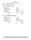
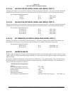
E 4.2.3.2 LOW LEVEL GLIDESLOPE
Quantity 1
Input Impedance, each leg
> 2.5 M
Ω
Reverse Fault Current
< 6.2
µ
amps
Signal Range
±
12 Dots
Input Voltage Range
±
0.9VDC
Input Filter
0.1 Second Low Pass,
±
10%
Input Type Differential
Common Mode Voltage Range (V
CM
)
11V
≥
V
CM
≥
-2V
Broken Wire Detect Input will be biased less than -15 dots
Pin Assignment (Signal Mnemonic):
+Up, Below Beam, Fly Up
+Down, Above Beam, Fly Down
J1-65
J1-46
(GSDEV_H)
(GSDEV_L)
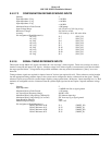
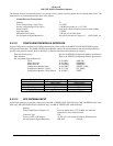
E 4.2.3.3 LOCALIZER DEVIATION OR LOW LEVEL GLIDESLOPE VALIDITY
This input can be configured as either a low level glideslope valid, or as a localizer deviation input. Installations that only
have the low level validity signal for glideslope can not activate the analog localizer input. See section 5.3.9 for more
information.
Quantity 1
Input Impedance, each leg
> 2.5 MΩ
Reverse Fault Current
< 6.2 µA
Input Filter
0.1 Second Low Pass, ± 10%
Input Type Differential
Common Mode Voltage Range (V
CM
)
11V ≥ V
CM
≥ -2V
Pin Assignment (Signal Mnemonic):
+
-
J1-30
J1-10
(GS_VAL_H)
(GS_VAL_L)