


Honeywell
MK XXII EGPWS Installation Manual
CAGE CODE: 97896 SCALE: NONE SIZE: A DWG NO: 060-4314-225 REV: C
SHEET
217
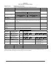
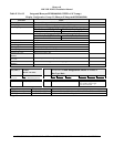
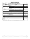
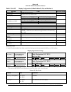
Table E 3.1.6-16 Bendix IN182A/IN812A Radar display (RDR 2000)
Function Value Reference section
Display Type Bendix IN182A/IN812A color Radar Display (RDR-2000 radar
system)
Sweep Type Sweep range +/- 50 degrees
Category 7, Options Select Group #1
TA&D Alternate Pop Up: False TA&D Alternate Pop Up: True
Auto Pop Up
Pop Up when the display is in the
proper mode.
Never Pop Up
Category 7, Options Select Group #1
Peaks Enabled: False Peaks Enabled: True
Peaks Mode
(Available -003)
Peaks Off Peaks On
Manual select Anytime WXR is on and display is in proper Mode
Manual deselect Anytime
Auto Range No
Moving Marker No
Overlay Page Yes; “TERR” centered at top of display.
“TERR” or Peaks Elevation located on upper right side of Terrain
image as of –003.
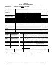
Display bus type Standard ARINC 453
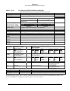
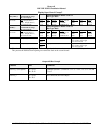
TERRAIN DISPLAY BUS #1
453TX_1
CONNECT TO:
A = J1-58
B = J1-59
Terrain Display data to switching relay/Symbol Generator
TERRAIN DISPLAY BUS #2
453TX_2
CONNECT TO:
A = J1-56
B = J1-57
Terrain Display data to switching relay/Symbol Generator
Note :
•
This config group is similar to config group 4 except warning inhibited message not seen on the overlay
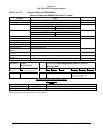
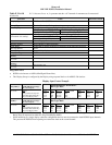
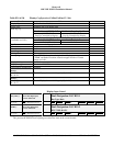
Display Input Control Group 2
CHANNEL
429_422RX_1
CONNECT TO:
WX-IND 429 out (range)
Bus 1 (Low Speed)
Fault Designation: DISPLAY BUS 1
Bus Type: Basic
A = J2-37
B = J2-36
Data
Mode (Display Word 1)
Range (Display Word 2)
Discrete Word (VP)
Reference
6.2.25
6.2.18
6.2.26
Label
270
271
273
Sig. Bits
Discrete
Discrete
Discrete
Range
Mode, Tilt, Gain
5-320NM
VP Mode, Bit 11
Signal Type
Basic
Basic
Basic
Resolution
N/A
N/A
N/A
Rate
100 ms
100 ms
100 ms
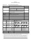
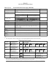
CHANNEL
429RX_3
CONNECT TO:
WX-IND 429 out (range)
Bus 2 (Low Speed)
Fault Designation: DISPLAY BUS 2
Bus Type: Basic
A = J2-41
B = J2-40
Data
Mode (Display Word 1)
Range (Display Word 2)
Discrete Word (VP)
Reference
6.2.25
6.2.18
6.2.26
Label
270
271
273
Sig. Bits
Discrete
Discrete
Discrete
Range
Mode, Tilt, Gain
5-320NM
VP Mode, Bit 11
Signal Type
Basic
Basic
Basic
Resolution
N/A
N/A
N/A
Rate
100 ms
100 ms
100 ms
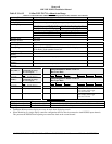
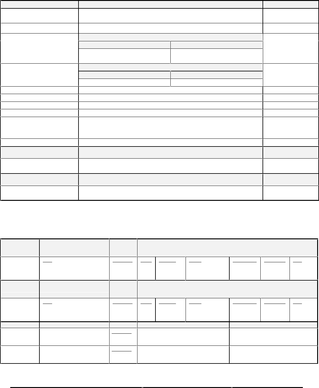
CONN PIN # REFERENCE NAME PIN FUNCTION Polarity/Configuration
J1-32 GND_DISC_12 Reference
4.2.7
6.6.18
Display Select Discrete #1 Type 1 (Momentary)
Gnd = Display Select Toggle
<not> Gnd = Normal
J1-31 GND_DISC_13 Reference
4.2.7
6.6.19
Display Select Discrete #2 Type 1 (Momentary)
Gnd = Display Select Toggle
<not> Gnd = Normal
* When interfacing to a single display controller configuration the bus must be connected to both EGPWS input channels.
This prevents the EGPWS from reporting an external bus fault on the second channel.