


Honeywell
MK XXII EGPWS Installation Manual
CAGE CODE: 97896 SCALE: NONE SIZE: A DWG NO: 060-4314-225 REV: C
SHEET
179
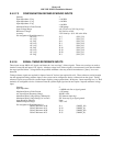
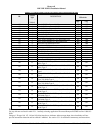
E 4.2.18.2 PCMCIA / SMARTCABLE PORT
One port is provided which meets the Motorola SPI characteristics. The PCMCIA / SmartCable interface allows for both the
uploading, and downloading of internal MK IV, VI, VIII and XXII EGPWS information. Using this interface system,
software and databases can be updated. Control of the upload/download process is accomplished by insertion of the
PCMCIA card / SmartCable to the MK IV, VI, VIII and XXII EGPWS front panel test connector. LEDs are provided on the
SmartCable for PCMCIA interface operation. The PCMCIA / SmartCable is not intended as an on-line/in-flight storage
medium and must be removed after completion of the upload/download operation.
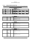
Electrical Characteristics Refer to the Motorola SPI specification
Data definition Refer to the Motorola SPI specification
Maximum Recommended Cable Length 2 meters
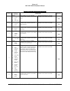
Pin Assignment (Signal Mnemonic):
Clock
Master Data Out
Master Data In
SmartCable Select
SmartCable +5VDC
SmartCable +5VDC Return
PCMCIA Card Present
SmartCable Ground
J3-7
J3-9
J3-8
J3-10
J3-6
J3-1
J3-2
J3-12, -13, -14
(SPICLK)
(SPIMOSI)
(SPIMISO)
(SPISEL_SC#)
(SC_PWR)
(GND)
(CARD_PRES#)
(GND)
NOTE: SmartCable +5VDC Return is common with RS-232 Maintenance Port common.
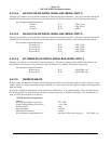
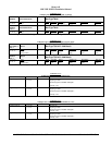
E 4.2.18.3 GSE PRESENT DISCRETE INPUT
A discrete input for test and Ground Support Equipment is provided. Grounding this pin indicates to the EGPWS that test or
Ground Support Equipment is connected to the system.
Active Threshold Voltage (Logic True) < 0.8 VDC
Inactive Threshold Voltage (Logic False) > 2.0 VDC
Input Impedance
> 20 K
Ω
Maximum Fault Current
< 500
µ
Amps
Pin Assignment (Signal Mnemonic): J3-11 (GSE_PRES#)
E 4.2.19 FRONT PANEL STATUS INDICATORS
The MK XXII EGPWC front panel provides three LEDs for indicating system and LRU status. A yellow LED labeled
“EXTERNAL FAULT” is activated when a signal fault external to the MK XXII EGPWS is detected. A green LED labeled
“COMPUTER OK” is activated when the MK XXII EGPWS itself is okay. A red LED labeled “COMPUTER FAIL” is
activated when the MK XXII EGPWS has detected an internal computer fault.
Refer to Product Specifications 965-1590-601 for a detailed discussion of status indications, recommended maintenance
actions, Self-Test activation and response.