


3.
Natural/Sour Gas. For air powered products that use natural/sour gas as the
power source, pipe away exhaust from the product. Exhaust system shall provide
safe removal or recirculation of gas and meet all applicable federal, state, and
local safety rules, codes and regulations.
n
Electrical Disconnect
Refer to the latest edition of the National Electrical Code (NFPA 70), Article 610-31.
Conductor Disconnecting Means
A disconnecting means that has a continuous ampere rating not less than that
computed in Sections 610-14(e) and (f) of NFPA 70 shall be provided between the
hoist contact conductors and the power supply. Such disconnecting means shall
consist of a motor-circuit switch, circuit breaker, or molded case switch. This
disconnecting means shall be as follows:
1. Readily accessible and operable from the ground or floor level.
2. Arranged to be locked in the open position.
3. Open all ungrounded conductors simultaneously.
4. Placed within view of the products contact conductors.
n
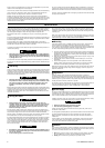
Shut-off Valve
On all air winch installations an emergency shut-off valve/switch should be installed
in the inlet line of the control valve, to provide the operator with a positive way of
stopping winch operation in the event of an emergency.
Valve shall be installed within easy range of the operator and positioned so that
activation can occur quickly, and any person in the area of the winch can also activate
the valve. Train people to its location and use.
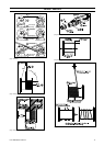
Refer to typical air powered winch installation Dwg. MHP2459 on page 11.
A. Air Flow; B. Open; C. Closed; D. Ball Valve; E. Fitting Nipple.
n
Guards
Ensure guards are in place and secure prior to operating winch. Ensure they do not
interfere with wire rope spooling or winch control operation.
Drum guards are available and recommended by Ingersoll Rand for all winch
installations. Guarding moving parts of a winch from accidental contact with
personnel shall be a prime consideration.
Additional guards, not provided by Ingersoll Rand, may be required to protect
hazardous areas around the winch. Guards should be used to protect against any
accidental contact with the winch and other system components.
Guards shall not cause an operator to work in a non-stable or ergonomically incorrect
position.
n
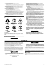
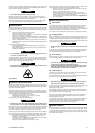
Construction Cage
WARNING
• Flame cutting or welding cage will produce toxic vapors which could cause
death or serious injury.
• Do not stack cages.
• Do not remove or cover warning labels.
• Mounting surface must be flat within 1/16 inch (2.9 mm) and sufficient
strength to prevent deflection on product.
• Refer to warning labels for fastener information.
WIRE ROPE SPOOLING
Read “WINCH OPERATION” section prior to operating winch.
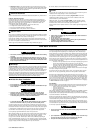
WARNING
• Never allow personnel to grab or touch the wire rope when the winch is being
operated.
• Immediately stop winch operation if anyone enters an area 3 ft. (1 m) in
front of the winch or the area behind the winch that is in line with the load
path. Refer to Dwg. MHP2451 on page 11. A. No-Zone; B. Keep Clear of this
Area; C. Keep Clear of Load Path.
n
Wire Rope
All Ingersoll Rand winches use wire rope to connect the load to the winch. Wire rope
consists of individual wires which form strands that wrap around the core. Wire rope
is attached to the winch drum and as the drum rotates it provides wire rope
movement. Wire rope sizes are stated as the diameter of a circle that would enclose
the wire rope strands, i.e. 3/8 in., 10 mm, etc. Each wire rope size is available in
various rope constructions and material. The construction and size requirements are
specified in the Product Information Manuals provided with the winch and are in
accordance with the designed capacity of the winch. Only use wire rope with
specifications that meet or exceed the rated winch and load capacity.
n
Initial Wire Rope Installation
DANGER
• Do not attempt to repair or use damaged wire rope.
• Do not modify wire rope diameter or anchor pocket to accommodate wire rope
anchor hardware.
WARNING
• Failure to match wire rope diameter with the correct wire rope anchor
hardware can cause wire rope to release from drum and drop the load.
• Ensure wire rope is installed in the proper over/under wound position, refer
to the data (name) plate and “Product Information Manual".
CAUTION
• To avoid air winch disc brake damage when installing wire rope, pressurize
brake with a minimum of 60 psi (4.1 bar) air from an auxiliary source.
The most important part of wire rope spooling is attaching wire rope to the drum.
Different methods are used to fasten the wire rope to the drum. Refer to the Product
Information Manuals for the specific method. Ensure wire rope anchor pocket guard
is installed when provided with the winch. Check wire rope length is sufficient for
task and does not exceed the top layer diameter, approved for the application.
Use only factory approved hardware to attach wire rope to drum.
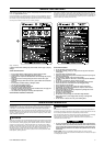
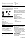
When initially spooling wire rope onto the winch drum make certain that it bends in
the same direction. Re-reel from the top of one reel to the top of another, or from
the bottom of one reel to the bottom of another. Refer to Dwg. MHP2450
on page 11. A. Correct; B. Overwound; C. Winch Drum; D. Wire Rope Spooling; E.
Spool; F. Underwound; G. Incorrect. It is also necessary to apply a tensioning load
to the wire rope to achieve good spooling. It is recommended that a local professional
rigging company be used to initially spool wire rope onto the drum.
When installing new wire rope it is important that all wraps of the first layer be tight
on the drum and adjoining the previous wrap. Open or wavy winding will result in
wire rope damage when multiple layers are used. Adjacent turns should be tight
against each other. If gaps occur between wraps, STOP winch and tap wire rope with
a composite or wooden mallet, so that the strands are snug but not interlocked. Do
not restart drum rotation until everyone is clear. The succeeding layers of wire rope
should wind across the preceding layer of wire rope without gaping or bunching.
Ensure that the correct length of wire rope is fitted. This is particularly important as
it may be necessary to fit specific lengths of wire rope for particular applications and
wire rope reeving combinations.
- Too short a wire rope could result in the wire rope completely paying out and
the wire rope anchorage on the drum having to carry the full load.
- Too long a wire rope could exceed the drum’s spooling capacity, causing the
wire rope to ride over the drum flange resulting in the load dropping, severe
damage, wire rope crushing or complete winch failure.
It is good practice to check the wire rope length whenever the structure is changed,
wire rope is changed or reeving altered.
To be certain that wire rope spools evenly on drum, use a spooling device to keep
tension on wire rope, approximately 10% of the working load is recommended.
Maintain a fleet angle between the lead sheave and winch of no more then 1-1/2˚.
A 2˚ fleet angle is allowable with grooved drums. Exceeding the specified fleet angle
can cause excessive friction, leading to heat build up or sparks. The lead sheave must
be on a center line with the drum, and for every inch (25 mm) of drum length, be at
least 1.6 ft (0.5 m) from the drum. Refer to Dwg. MHP2449 on page 11. A. Sheave;
B. Fleet Angle; C. Drum Flange. For additional sheave information refer to “Rigging”
in “WINCH OPERATION” section on page 8.
Tight Winding:
The entire length of wire rope should be wound on the drum tightly and correctly as
this will facilitate good winding during operation. Poor or incorrect spooling can:
- shorten wire rope life cause erratic winch operation.
- cause wire rope to drop.
- cause wire rope to bunch.
- be less than distance to flange dimension.
Refer to Dwg. MHP2453 on page 11 for spooling conditions to be avoided. A. Sheave
Flange and Wire Rope Wear; B. Wire Rope Wear; C. Wire Rope Wound too Tightly
Compressed; D. Uneven Spooling Bunched Wire Rope; E. or; F. When the Fleet Angle
is too Small the Result is Poor Winding.
Spooling area should be clean and free of debris. Care should be taken to ensure that
wire rope is clean and properly lubricated as it is spooled onto drum. Wire rope should
not be allowed to drag or touch the ground during spooling.
Use only clean serviceable wire rope on winches. Inspect wire rope carefully as it is
being spooled onto drum. Watch for broken or loose strands or other signs of damage
or unserviceable wire rope. Refer to this manual and the Product Information Manuals
for wire rope inspection requirements.
WARNING
• Use of wire rope sizes other than recommended will greatly decrease the life
of the wire rope.
CAUTION
• Upon completion of spooling and prior to final installation, secure wire rope
to drum. This will prevent wire rope from loosening on the drum.
• Keep all non-essential personnel clear of spooling area.
Form MHD56250 Edition 5 7