


Various controls are available with the winches and are dependent on power source,
location to winch and degree of control required.
For air winches, full flow control valves are normally used which are connected directly
to the winch motor. These have a lever, which is actuated forward and back for
direction control. The degree of lever movement controls drum speed.
Pendant controls are typically used on electric winches but are also available on
pneumatic and hydraulic winches. This type of control sends a signal back to a valve
or control panel mounted to the winch. This control allows the owner/user to be some
distance from the winch. Pendant controls have levers or buttons which control
forward and reverse drum rotation.
The use of pendant controls require additional safety considerations, as the owner/
operator may not be at the winch to observe drum rotation or wire rope spooling.
Operators must maintain visual contact with the load, drum and wire rope at all times.
All winch controls are available with an emergency stop button which when activated
will stop winch movement.
INSTALLATION
Inspect shipping package for any signs of shipping damage. Remove shipping material
carefully and inspect winch for any damage. Pay close attention to hoses, fittings,
brackets, handles, valves, or any other items that attach or protrude from winch. Any
item that appears damaged no matter how slight shall be inspected and a
determination made as to its suitability for use prior to winch being placed into
service.
Ensure that warning and operation labels and tags are not removed or covered during
or after the installation process. Contact the factory for replacement labels if labels
become damaged or unreadable.
Ensure that data (name) plate is attached and readable. Refer to the Product
Information Manuals for additional information. Replacement data (name) plates are
available when complete winch serial number is provided.
If winches are repainted, ensure labels and tags are protected and the protection is
removed after painting.
CAUTION
•
Owners and users are advised to examine specific, local or other regulations,
including American Society of Mechanical Engineers and/or OSHA Regulations
which may apply to a particular type of use of this product before installing
or putting winch to use.
It is the owner’s and user’s responsibility to determine the suitability of a product for
any particular use. Review all applicable industry, trade association, federal and state
regulations.
n
Site Survey
Inspect site where product will be mounted. Ensure that mounting surface will be big
enough for product and operator. Refer to Product Information Manuals for specific
information on mounting surface requirements, attaching hardware and power supply
requirements. Survey site to ensure operator ability to reach all controls comfortably
and observe loads during operation.
WARNING
• Supporting structures and load-attaching devices used in conjunction with
this product must meet or exceed the design safety factor to handle the rated
load, plus the weight of the product and attached equipment. This is the
customer’s responsibility. If in doubt, consult a registered structural
engineer.
When installing the product ensure that installation personnel are trained and factory
certified to perform the tasks. The use of licensed electricians or registered structural
engineers may be required. Use of trained, certified personnel will ensure safe
installation and that all items used in the installation will meet federal, state and
local code requirements.
n
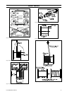
Moving the Winch
WARNING
• During movement of the winch, ensure that winch does not pass over
personnel. Winches raised higher than 5 ft (2.5 m) during move should use
“tag lines”. These lines should be long enough to allow personnel to be a
safe distance from the winch. Attach them, opposite each other, to help
stabilize load during movement.
Once the winch is ready to move to the mounting site, weight of complete winch
must be determined. This will ensure that lifting equipment with enough capacity is
used. The basic weight of the winch is found in the winch Product Information
Manuals, however, the addition of wire rope, guards, air preparation packages or other
owner added items can cause the finished weight to be much greater.
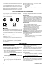
On irregular shaped loads where it cannot be easily determined, the rigger must guess
where the center of gravity lies. Try to lift with the hook over that point and then
correct it by making minor adjustments, moving the hook, load and sling suspension
until a satisfactory result is obtained. The load will always tilt until the center of
gravity is directly beneath the load hook, this is an indication of the direction in
which to shift the slings.
CAUTION
• The addition of items to the winch can affect the center of GRAVITY, even if
the winch is equipped with lifting eyes. On the initial lift ensure winch does
not “roll, tilt or shift”.
• Do not use lifting eyes on motor to lift winch.
To rig a winch for moving, use nylon slings or hooks of the correct capacity in the
lifting eyes. Rig the winch in a manner to prevent any “rolling or shifting” during
movement. Ensure that lifting equipment has clear access and can easily reach the
mounting site.
With winch rigged to move and the correct lifting equipment attached, on the initial
lift, only lift winch a couple of inches (50 - 75 mm) and determine stability of rigging
before continuing. If winch is stable, continue with installation.
n
Mounting
Check that sufficient space is available to operate winch control, manual brake or
other components and to make inspections or adjustments when necessary.
Do not weld on winches. Welding can change the physical properties of some of the
parts, which can affect strength or durability. Excessive heat can be generated which
can affect and/or damage internal parts such as seals and bearings.
1. The winch mounting surface must be flat and of sufficient strength to handle the
rated load plus the weight of the winch and attached equipment. An inadequate
foundation may cause distortion or twisting of the winch uprights and side rails
resulting in winch damage.
2. Make sure the mounting surface is flat to within 0.005 inch (0.127 mm) per inch
of drum length. Shim winch if necessary.
3. Mounting bolts must be Grade 8 or better. Use self locking nuts or nuts with
lockwashers.
4. Ensure mounting bolts are of the size specified in the Product Information
Manuals. Tighten evenly and torque to specifications. If fasteners are plated,
lubricated or a thread locking compound is used, torque appropriately.
When sheaves are part of the winch installation ensure the mounting and support of
these items meet load capacity ratings. Refer to “Rigging” section on page 10 to
determine sheave size.
n
Ergonomics
Operator’s position at the controls should allow the operator to maintain a
comfortable, well-balanced posture. The position should also allow easy access to all
controls without reaching. In this position, the operator should be able to view the
load during entire cycle of movement. This position along with recommended guards
should provide the maximum protection to operator.
The operator’s position should also be free of obstructions both overhead and on the
sides. The operators area must be well ventilated, kept oil free and clear of
unnecessary equipment/tools etc. and be provided with a non-skid surface.
n
Power Supply
For all types of this product there is a recommended power supply input for the best
performance, refer to the Product Information Manuals. A power supply of less than
recommended will result in reduced product performance and may cause some items
such as brakes, overload valves or limit switches to function incorrectly.
Exceeding the power supply can cause product to exceed rated performance. Brakes,
overload sensors, limit switches/valves may not function correctly.
WARNING
• Ensure that all power supply connections are tight.
• Check electrical grounding (earth) is complete.
Comply with any other safety precautions to ensure a good, safe, power source
connection at the product.
Air and hydraulic powered products require filtration before the control valve. Refer
to Product Information Manuals for specific filtration level, type and location.
Without filtration, contaminates can enter the system and cause components to
malfunction.
Electric products can also be affected by contamination. Keep motor and controls
clean. Ensure phase, cycle and voltage of motor magnetic reversing starter and
controls all match the electrical service being used.
n
Exhaust
On pneumatic powered products, careful consideration must be given to the exhaust.
Make sure products are positioned in a well ventilated area. Do not allow personnel
to stand in the exhaust stream as this can result in injury.
1.
Noise. Using piping or tubing to move exhaust away from operator can reduce
this. The addition of a muffler is also recommended to reduce noise level.
2.
Misting. Clean and remove any build-up of oily residue in area.
6
Form MHD56250 Edition 5