


Section 1
General Information
5-16 Troubleshooting MN722
Electrical Noise Considerations Continued
Special Drive Situations
For severe noise situations, it may be necessary to reduce transient voltages in the wires
to the motor by adding load reactors. Load reactors are installed between the control and
motor.
Reactors are typically 3% reactance and are designed for the frequencies encountered in
PWM drives. For maximum benefit, the reactors should be mounted in the drive
enclosure with short leads between the control and the reactors. Baldor can deliver line
and load reactors that will reduce ripple current and improve motor life.
Control Enclosures Motor controls mounted in a grounded enclosure should also be connected to earth
ground with a separate conductor to ensure best ground connection. Often grounding
the control to the grounded metallic enclosure is not sufficient. Usually painted surfaces
and seals prevent solid metallic contact between the control and the panel enclosure.
Likewise, conduit should never be used as a ground conductor for motor power wires or
signal conductors.
Special Motor Considerations
Motor frames must also be grounded. As with control enclosures, motors must be
grounded directly to the control and plant ground with as short a ground wire as possible.
Capacitive coupling within the motor windings produces transient voltages between the
motor frame and ground. The severity of these voltages increases with the length of the
ground wire. Installations with the motor and control mounted on a common frame, and
with heavy ground wires less than 10 ft. long, rarely have a problem caused by these
motor–generated transient voltages.
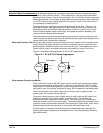
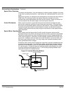
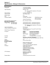
Sometimes motor frame transient voltages are capacitively coupled to feedback devices
mounted on the motor shaft. To prevent this problem, add electrical isolation between
the motor and the feedback device. The most simple isolation method, shown in Figure
5-2, has two parts: 1) A plate of electrical insulating material placed between the motor
mounting surface and the feedback device. 2) An insulating coupling between motor
shaft and the shaft of the feedback device.
Figure 5-2 Isolated Mounting Method
Insulating plate
Insulating Coupling
Encoder or other
feedback device
Mounting bracket