


Section 1
General Information
Receiving & Installation 3-35MN722
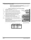
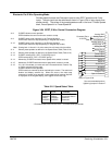
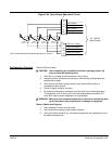
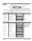
Figure 3-30 Opto-Output Equivalent Circuit
19
20
21
22
41
42
43
Opto Output 1
Opto Output 2
Opto Output 3
Opto Output 4
Opto Out 1 Return
J1
Opto Out 2 Return
Opto Out 3 Return
44
Opto Out 4 Return
18
PC865
50mA max
10 – 30VDC
Opto Outputs
PC865
50mA max
PC865
50mA max
PC865
50mA max
See recommended terminal tightening torques in Section 7.
Pre-Operation Checklist Check of Electrical Items
CAUTION: After completing the installation but before you apply power, be
sure to check the following items.
1. Verify AC line voltage at source matches control rating.
2. Inspect all power connections for accuracy, workmanship and tightness and
compliance to codes.
3. Verify control and motor are grounded to each other and the control is
connected to earth ground.
4. Check all signal wiring for accuracy.
5. Be certain all brake coils, contactors and relay coils have noise suppression.
This should be an R-C filter for AC coils and reverse polarity diodes for DC
coils. MOV type transient suppression is not adequate.
WARNING: Make sure that unexpected operation of the motor shaft during start
up will not cause injury to personnel or damage to equipment.
Check of Motor and Coupling
1. Verify freedom of motion of motor shaft.
2. Verify that motor coupling is tight without backlash.
3. Verify the holding brakes if any, are properly adjusted to fully release and set to
the desired torque value.