


Section 1
General Information
Receiving & Installation 3-11MN722
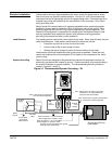
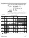
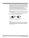
“EK” suffix (“EK” Controls are input phase sensitive. Check all connections).
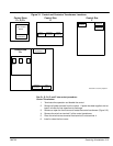
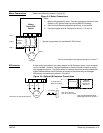
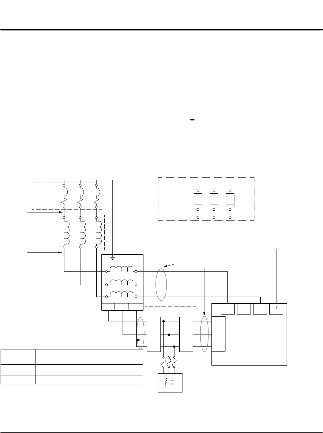
The AC power and motor connections are shown in Figure 3-4. Overloads are not
required. The 22H control has an electronic I
2
t motor overload protection. If motor
overloads are desired, they should be sized according to the manufacturers specifications
and installed between the motor and the T1, T2 and T3 terminals of the control.
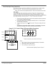
1. Connect the incoming AC power wires from the protection devices to terminals
A1, B1 and C1 of the 3% line reactor.
2. Connect A2, B2 and C2 3% line reactor terminals to the L1, L2 and L3 of the
boost regulator.
3. Connect X1, X2 and X3 boost regulator terminals to X1, X2 and X3 of the control.
4. * Connect earth ground to the “ ” of the control. Be sure to comply with local codes.
5. Connect boost regulator terminals L1A, L2A and L3A to Filter terminals J1-1,
J1-2 and J1-3.
6. Connect filter terminals J2-1, J2-2 and J2-3 to control terminals L1A, L2A and L3A.
* Grounding by using conduit or panel connection is not adequate. A separate
conductor of the proper size must be used as a ground conductor.
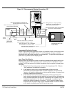
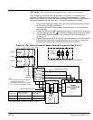
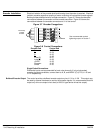
Figure 3-4 “EK” Control 3 Phase AC Power and Motor Connections (Size D, E & F)
L1 L2 L3
Alternate *
Fuse
Connection
Note 1
L1 L2 L3
X1 X2 X3
* Circuit
Breaker
Earth
* Optional components not provided with 22H Control.
See Recommended Tightening Torques in Section 7.
Note 2
Baldor
Series 22HXXX-EK
Control
3% Line
Reactor
Note 1
Note 2
A1 B1 C1
C2
A1 B1 C1
Note 3
Boost
Regulator
L1
L2
L3
X1
X2
X3
J1 J2
1
2
3
1
2
3
Filter
L1A
L2A
L3A
A2 B2
L1A L2A L3A
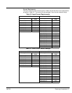
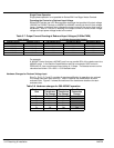
Control Size
Boost Regulator to
Filter (5 ft. max.)
Filter to Control
(10 ft. max.)
D & E
F
14AWG (2.08 mm
2
)
10AWG (5.26 mm
2
)
14AWG (2.08 mm
2
)
10AWG (5.26 mm
2
)
Phase Sensitive Inputs
Phase Sensitive Inputs
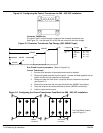
Notes:
1. See “Protective Devices” described
previously in this section.
2. Shield wires inside a metal conduit.
3. 3% Line Reactor is required at input.