


Section 1
General Information
3-22 Receiving & Installation MN722
Inverter Control Board Connections
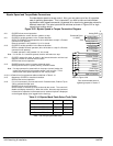
Ten operating modes are available in the Series 22H vector control. These operating
modes define the basic motor control setup and the operation of the input and output
terminals. After the circuit connections are completed, the operating mode is selected by
programming the Level 1 Input block, Operating Mode parameter.
Available operating modes include:
• Keypad Control
• Standard Run, 3 Wire Control
• 15 Speed, 2 Wire Control
• Three Speed, 2 Wire Control
• Three Speed, 3 Wire Control
• Serial
• Bipolar Speed or Torque
• Process Control
• EPOT, 2 Wire Control
• EPOT, 3 Wire Control
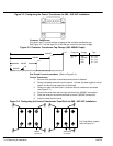
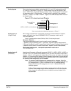
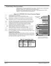
Each mode requires connections to the J1 terminal strip (except keypad and serial
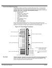
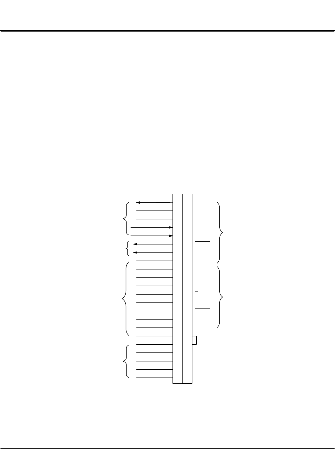
modes, all connections are optional). The J1 terminal strip is shown in Figure 3-16. The
connection of each input or output signal is described in the following pages.
Figure 3-16 Control Signal Connections
8
9
10
11
12
13
14
15
16
17
18
19
20
21
22
Input #1
Input #2
Input #3
Input #4
Input #5
Input #6
Input #9
Opto In Common
J1
Analog GND
Analog Input 1
Pot Reference
Analog Input +2
Analog Input -2
Analog Out 1
Analog Out 2
Opto Out #1
Opto Out #2
Opto Out #3
Opto Out #4
1
2
3
4
5
6
7
See recommended terminal tightening torques in Section 7.
30
31
32
33
34
35
36
37
38
39
40
41
42
43
44
23
24
25
26
27
28
29
Common
+24VDC
A
A
B
B
INDEX
INDEX
+5VDC
Opto In Power
Opto Out #1 Return
Opto Out #2 Return
Opto Out #3 Return
Opto Out #4 Return
Common
A
A
B
B
INDEX
INDEX
Not Used
Refer to Encoder Installation
Refer to Buffered Encoder Output
Input #7
Input #8
Refer to opto isolated Outputs
Refer to opto isolated Inputs
Refer to Analog Outputs
Refer to Analog Inputs
Note: J1-18 and J1-41 are connected
together on the control circuit
board.
J1-39 & 40 Jumper as shown to power
the opto inputs from the
internal +24VDC supply.
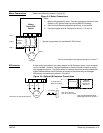
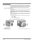
Serial Mode The Serial operating mode requires one of the optional Serial Interface expansion boards
(RS232 or 422/485). Installation and operation information for these serial expansion
boards is provided in Serial Communications expansion board manual MN1310. This
manual is shipped with the serial expansion board.