


Section 1
General Information
Programming & Operation 4-21MN722
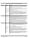
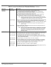
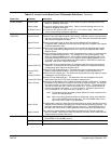
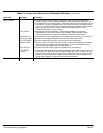
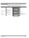
Table 4-5 Inverter Control Board Level 2 Parameter Definitions - Continued
Block Title Parameter Description
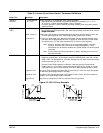
BRAKE ADJUST Resistor Ohms The dynamic braking resistor value in ohms. Refer to dynamic braking manual or call
Baldor for additional information.
Resistor Watts
DC Brake Current
The dynamic braking resistor watts rating. Refer to dynamic braking manual or call
Baldor for additional information.
The amount of DC injection brake current. 0% = Flux current, 100% = Motor rated
current. (Used during encoderless operation).
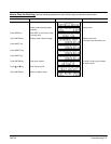
PROCESS
CONTROL
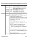
Process Feedback
Process Inverse
Setpoint Source
Setpoint Command
Set PT ADJ Limit
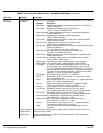
Process ERR TOL
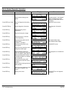
Process PROP
Gain
Process INT Gain
Process DIFF Gain
Follow I:O Ratio
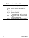
Follow I:O Out
Master Encoder
Sets the type of signal used for the process feedback signal.
Causes the process feedback signal to be inverted. Used with reverse acting processes
that use a unipolar signal such as 4-20mA. If “ON”, 20mA will decrease motor speed
and 4mA will increase motor speed.
Sets the source input signal to which the process feedback will be compared.
If “Setpoint CMD” is selected, the fixed value of the set point is entered in the Setpoint
Command parameter value.
Sets the value of the setpoint the control will try to maintain by adjusting motor speed.
This is only used when the Setpoint Source is a fixed value “Setpoint CMD” under
Setpoint Source.
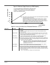
Sets the maximum speed correction value to be applied to the motor (in response to the
maximum feedback setpoint error). For example, if the max motor speed is 1750
RPM, the setpoint feedback error is 100% and the setpoint adjustment limit is 10%,
the maximum speed the motor will run in response to the setpoint feedback error is
±175 RPM. If at the process setpoint, the motor speed is 1500 RPM, the maximum
speed adj limits is then 1325 to 1675 RPM.
Sets the width of the comparison band (% of setpoint) with which the process input is
compared. The result is that if the process input is within the comparison band the
corresponding Opto Output will become active.
Sets the PID loop proportional gain. This determines how much adjustment to motor
speed or torque (within the Set PT ADJ Limit) is made to reduce process error.
Sets the PID loop Integral gain. This determines how quickly the motor speed or torque
is adjusted to correct long term error.
Sets the PID loop differential gain. This determines how much adjustment to motor
speed (within the Set PT ADJ Limit) is made for transient error.
Sets the ratio of the Master to the Follower in Master/Follower configurations. Requires
the Master Pulse Reference/ Isolated Pulse Follower expansion board. For example,
the master encoder you want to follow is a 1024 count encoder. The follower motor
you wish to control also has a 1024 count encoder on it. If you wish the follower to
run twice the speed of the master, a 1:2 ratio is entered. Fractional ratios such as
0.5:1 are entered as 1:2. Ratio limits are (1-65,535) : (1-20).
Note: The Master Encoder parameter must be defined if a value is entered in the
Follow I:O Ratio parameter.
Note: When using Serial Communications to operate the control, this parameter
value is the MASTER portion of the ratio. The FOLLOWER portion of the
ratio is set in the Follow I:O Out parameter.
This parameter is used only when Serial Communications is used to operate the control.
A Master Pulse Reference/ Isolated Pulse Follower expansion board is required. This
parameter represents the FOLLOWER portion of the ratio. The MASTER portion of
the ratio is set in the Follow I:O Ratio parameter when using Serial operating mode.
Only used if an optional Master Pulse Reference/Isolated Pulse Follower expansion
board is installed. Defines the number of pulses per revolution of the master encoder.
Programmed into follower drives only.
COMMUNICATIONS Protocol Sets the type of communication the control is to use, RS-232 ASCII, RS-485 ASCII,
RS-232 BBP or RS-485 BBP protocol.
Baud Rate Sets the speed at which communication is to occur.
Drive Address Sets the address of the control for communication.