


Section 1
General Information
Receiving & Installation 3-23MN722
Keypad Mode Connections The Keypad operating mode allows the control to be operated from the keypad. This
mode requires no connections to J1. However, the Enable, Stop and External Trip inputs
may optionally be used. All other opto inputs remain inactive. The analog outputs and
opto-outputs remain active at all times. See Figure 3-17.
Parameter Selection
For operation in Keypad mode, set the Level 1 Input block, Operating Mode parameter to
Keypad. The STOP key can operate in two ways:
S Press STOP key one time to brake or coast to stop.
S Press STOP key two times to disable control.
To use the Enable input, J1-8 must be connected and the Local Enable INP parameter in
the Level 2 Protection block must be set to ON. The Enable line is normally closed.
When opened, the motor will COAST to a stop. When the enable line is again closed, the
motor will not start until a new direction command is received from the keypad.
To use the Stop input, J1-11 must be connected and the Level 1 Keypad Setup block,
LOC. Hot Start parameter must be set to ON. The Stop line is normally closed. When
opened, the motor will COAST or REGEN to a stop depending upon the setting of Level 1
Keypad Setup block Keypad Stop Mode parameter value. Closing the input will
immediately start the motor.
The External Trip input causes a fault condition during a motor over temperature
condition (when normally closed input opens). The External Trip input (J1-16) must be
connected and the External Trip parameter in the Level 2 Protection block must be set to
“ON”. When J1-16 is opened, an external trip fault occurs. The control will disable and
the motor coasts to a stop. An external trip fault is displayed on the keypad display (also
logged into the fault log).
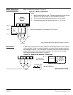
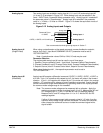
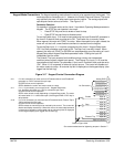
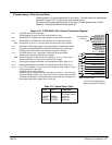
Figure 3-17 Keypad Control Connection Diagram
No Connection
See recommended terminal tightening torques in Section 7.
Refer to Figure 3-26.
8
9
10
11
12
13
14
15
16
17
Input #1
Input #2
Input #3
Input #4
Input #5
Input #6
Input #9
Opto In Common
Analog GND
Analog Input 1
Pot Reference
Analog Input +2
Analog Input -2
Analog Out 1
Analog Out 2
1
2
3
4
5
6
7
Input #7
Input #8
J1
J1-8 If J1-8 is connected, you must set Level 2 Protection block, Local Enable INP
parameter to “ON” to activate the opto input.
CLOSED allows normal operation.
OPEN disables the control and motor coasts to a stop.
J1-11 If J1-11 is connected, you must set Level 1 Keypad Setup block,
Loc. Hot Start parameter to to “ON” to activate the opto input.
CLOSED allows normal operation.
OPEN motor decels to stop (depending on Keypad Stop mode). The motor
will restart when J1-11 closes after open (if the keypad FWD or REV key is
still pressed).
J1-16 If J1-16 is connected, you must set Level 2 Protection block, External Trip to
“ON” to activate the opto input.
CLOSED allows normal operation.
OPEN causes an external trip to be received by the control. The control will
disable and display external trip. When this occurs, the motor stop command
is issued, drive operation is terminated and an external trip fault is displayed
on the keypad display (also logged into the fault log).
Enable
Stop
External Trip