


Section 1
General Information
3-36 Receiving & Installation MN722
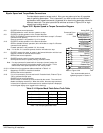
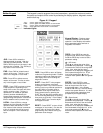
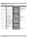
Power-Up Procedure This procedure will help get your system up and running in the Keypad mode quickly.
This will allow you to prove the motor and control operation. This procedure assumes
that the control and motor are correctly installed (see Section 3 for procedures) and that
you have an understanding of the keypad programming & operation procedures. It is not
necessary to wire the terminal strip to operate the motor in the Keypad mode.
Initial Conditions
Be sure the control and motor are wired according to the procedures described previously
in this manual. Become familiar with the keypad programming and keypad operation of
the control as described in Section 4 of this manual.
1. Disconnect the load (including coupling or inertia wheels) from the motor shaft if
possible.
2. Verify that all enable inputs to J1-8 are open.
3. Turn power on. Be sure no errors are displayed.
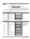
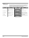
4. Set the Level 1 Input block, Operating Mode parameter to “KEYPAD”.
5. Set the Level 2 Output Limits block, “OPERATING ZONE” parameter as desired
(STD CONST TQ, STD VAR TQ, QUIET CONST TQ or QUIET VAR TQ).
6. Enter the following motor data in the Level 2 Motor Data block parameters:
Motor Voltage (Nameplate, VOLTS)
Motor Rated Amps (Nameplate, FLA)
Motor Rated Speed (Nameplate, RPM)
Motor Rated Frequency (Nameplate, HZ)
Motor Mag Amps (Nameplate, NLA)
Encoder Counts
7. At the Level 2 Motor Data, go to CALC Presets and select YES (using the up
arrow key). Press ENTER and let the control calculate the preset values for the
parameters that are required for control operation.
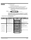
8. Disconnect the motor from the load (including coupling or inertia wheels). If the
load can not be disconnected, refer to Section 6 and manually tune the control.
After manual tuning, perform steps 10, 11, 15, 16 and 17.
WARNING: The motor shaft will rotate during this procedure. Be certain that
unexpected motor shaft movement will not cause injury to
personnel or damage to equipment.
9. At the Level 2 Autotune block, perform the following tests:
CMD OFFSET TRIM
CUR LOOP COMP
STATOR R1
FLUX CUR SETTING
ENCODER TESTS
SLIP FREQ TEST
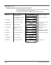
10. Set the Level 2 Output Limits block, “MIN OUTPUT SPEED” parameter.
11. Set the Level 2 Output Limits block, “MAX OUTPUT SPEED” parameter.
12. Remove all power from the control.
13. Couple the motor to its load.
14. Turn power on. Be sure no errors are displayed.
15. Go to Level 2 Autotune block, and perform the SPD CNTRLR CALC test.
16. Run the drive from the keypad using one of the following: the arrow keys for
direct speed control, keypad entered speed or the JOG mode.
17. Select and program additional parameters to suit your application.
The control is now ready for use the in keypad mode. If a different operating mode is
desired, refer to Section 3 for control connection diagrams and Section 4 Programming
and Operation.