


Section 1
General Information
3-16 Receiving & Installation MN722
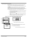
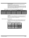
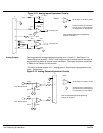
Encoder Installation Electrical isolation of the encoder shaft and housing from the motor is required. Electrical
isolation prevents capacitive coupling of motor noise that will corrupt the encoder signals.
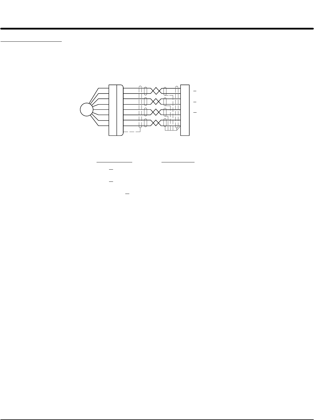
Baldor provides shielded wire for encoder connection. Figure 3-7 shows the electrical
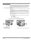
connections between the encoder and the encoder connector. Figure 3-8 shows the
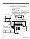
connections between the encoder connector and J1 of the control.
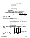
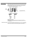
Figure 3-7 Encoder Connections
A
A
B
B
C
C
+5V
COMMON
23
24
25
26
27
28
29
30
J1
Electrically
Isolated
Encoder
See recommended terminal
tightening torques in Section 7.
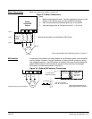
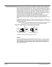
Figure 3-8 Control Connections
Encoder End Control End
A J1-23
A J1-24
B J1-25
B J1-26
Index(C) J1-27
Index(C) J1-28
+5VDC J1-29
Common J1-30
Shield J1-30
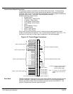
Single Ended Connections
Differential inputs are recommended for best noise immunity. If only single ended
encoder signals are available, connect them to A, B, and INDEX (C) (J1-23, J1-25 and
J1-27 respectively).
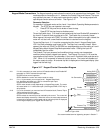
Buffered Encoder Output The control provides a buffered encoder output on pins J1-31 to J1-38. This output may
be used by external hardware to monitor the encoder signals. It is recommended that this
output only drive one output circuit load (a 26LS31 type device drives this output).