


Section 1
General Information
Receiving & Installation 3-19MN722
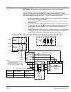
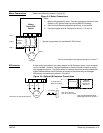
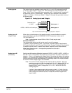
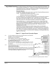
Analog Inputs Two analog inputs are available: analog input #1 (J1-1 and J1-2) and analog input #2
(J1-4 and J1-5) as shown in Figure 3-12. Either analog input may be selected in the
Level 1 INPUT block, Command Select parameter value. Analog input #1 is selected if
the parameter value is “Potentiometer”. Analog input #2 is selected if the parameter
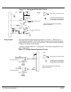
value is “+/-10Volts, +/-5 Volts or 4-20mA”. Figure 3-13 shows the equivalent circuits of
the Analog Inputs.
Figure 3-12 Analog Inputs and Outputs
J1
Analog GND
Analog Input 1
Pot Reference
Analog Input +2
Analog Input -2
1
2
3
4
5
Analog Input 1
Analog Input 2
Command Pot or
0-10VDC
±5VDC, ±10VDC or 4-20 mA Input
See recommended terminal tightening torques in Section 7.
5KW
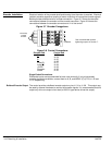
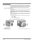
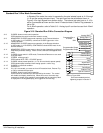
Analog Input #1 When using a potentiometer as the speed command, process feedback or setpoint
(Single Ended) source, the Level 1 Input block COMMAND SELECT parameter must be set to
“POTENTIOMETER”.
Note: A potentiometer value of 5kW to 10kW, 0.5 watt may be used.
Parameter Selection
The single ended analog input #1 can be used in one of three ways:
1. Speed or Torque command (Level 1 Input block, Command Select=Potentiometer).
2. Process Feedback (Level 2 Process Control block, Process Feedback=Potentiometer).
3. Setpoint Source (Level 2 Process Control block, Setpoint Source=Potentiometer).
When using Analog Input #1, the respective parameter must be set to
“POTENTIOMETER”.
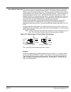
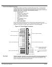
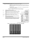
Analog Input #2 Analog input #2 accepts a differential command 0-5VDC, 0-10VDC, ±5VDC, ±10VDC or
(Differential) 4-20 mA. If pin J1-4 is positive with respect to pin 5, the motor will rotate in the forward
direction. If pin J1-4 is negative with respect to pin 5, the motor will rotate in the reverse
direction. JP1 must be set for voltage or current operation as required. Analog Input #2
can be connected for single ended operation by grounding either of the inputs, provided
the common mode voltage range is not exceeded.
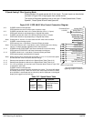
Note: The common mode voltage can be measured with a voltmeter. Apply the
maximum command voltage to analog input 2 (J1-4, 5). Measure the AC and
DC voltage across J1-1 to J1-4. Add the AC and DC readings together.
Measure the AC and DC voltage from J1-1 to J1-5. Add the AC and DC
readings together.
If either of these measurement totals exceeds a total of ±15 volts, then the
common mode voltage range has been exceeded. To correct this condition,
either change the command source or isolate the command signal with a
signal isolator.