


Section 1
General Information
Receiving & Installation 3-21MN722
Control Circuit Connections
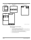
There are two control boards in a Series 22H Vector Control. The Converter Control
Board is used to rectify and process the incoming power. The Inverter Control Board
provides the inverting and power output functions. The keypad is normally connected to
the Inverter Control Board. Each converter board has its own J1 terminal strip. The
Inverter Control Board provides the user interface for most external connections.
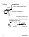
Converter Control Board Connections
All necessary connections for the Converter Control Board have been made at the factory
prior to shipment.
The jumper between J1-8 and J1-17 provides the enable signal to allow converter
operation. The jumper between J1-39 and J1-40 provides +24VDC from the internal
supply to allow the opto isolated input at J1-8 to operate. These jumpers should remain
installed at all times.
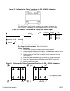
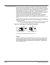
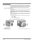
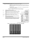
Sometimes it is necessary to troubleshoot the converter section using the isolated opto
outputs. Figure 3-15 shows how to connect external relays to the board to “Sink” or
“Source” the relay current.
The function of each opto output is as follows: (these functions cannot be changed)
J1-19 Ready
J1-20 At Voltage
J1-21 Fault
J1-22 Overtemperature Warning
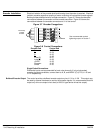
Figure 3-15 Converter Control Board Opto Output Wiring
Using Internal Supply
(Sinking the Relay Current)
Optional
Customer
Supplied
Relays &
Diodes
Using Internal Supply
(Sourcing the Relay Current)
17
18
19
20
21
22
24Com
39
41
42
43
44
+24VDC
Optional
Customer
Supplied
Relays &
Diodes
17
18
19
20
21
22
24Com
41
42
43
44
+24VDC
39
Note: Add appropriately rated
protective device for AC relay
(snubber) or DC relay (diode).
See recommended terminal tightening torques in Section 7.