


Section 1
General Information
Troubleshooting 5-11MN722
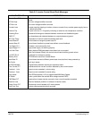
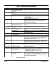
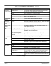
Table 5-4 Inverter Section Troubleshooting Continued
INDICATION POSSIBLE CAUSE CORRECTIVE ACTION
Motor has wrong
response to
Speed Command
Analog input common mode voltage
may be excessive.
Connect control input source common to control common to minimize
common mode voltage. Maximum common mode voltage at terminals
J1-4 and J1-5 is ±15VDC referenced to chassis common.
Incorrect MIN or MAX speed
settings.
Check Level 2 Output Limits block, MIN Output Speed and MAX Output
Speed parameter values and adjust as needed.
Analog offset trim is incorrectly set. Re-run “Offset Trim” autotune test.
Speed gain value is too large. Reduce the Level 1 Vector Control block, Speed PROP Gain and
Speed INT Gain parameter values.
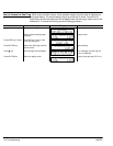
Motor Shaft
Oscillates back
and forth
Incorrect encoder alignment
direction.
Change the Feedback Align parameter in the Level 1 Vector Control block.
If Reverse, set to Forward. If Forward, set to Reverse.
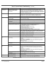
Motor Shaft
rotates at low
speed regardless
of commanded
speed
Incorrect encoder alignment
direction.
Check encoder connections.
Change the Feedback Align parameter in the Level 1 Vector Control block.
If Reverse, set to Forward. If Forward, set to Reverse.
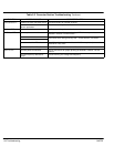
Motor Shaft
rotates in wrong
direction
Incorrect encoder wiring. Reverse the A and A or B and B encoder wires at the J1 input to control
and change encoder direction in the Feedback Align parameter in the
Level 1 Vector Control block.
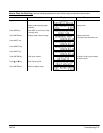
Motor Will Not Not enough starting torque. Increase Current Limit setting.
Start
Motor overloaded. Check for proper motor loading.
Check couplings for binding.
Verify proper sizing of control and motor.
Motor may be commanded to run
below minimum speed setting.
Increase speed command or reduce minimum speed setting.
Incorrect Command Select
parameter.
Change Command Select parameter to match wiring at J1.
Incorrect speed command. Verify control is receiving proper command signal at J1.
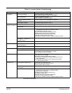
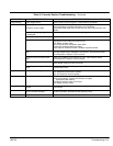
Motor Will Not Max Output Speed set too low. Adjust Level 2 Output Limits block, MAX Output Speed parameter value.
Reach Maximum
Speed
Motor overloaded. Check for mechanical overload. If unloaded motor shaft does not rotate
freely, check motor bearings.
Improper speed command. Verify control is set to proper operating mode to receive speed command.
Verify control is receiving proper command signal at input terminals.
Check velocity loop gains.
Speed potentiometer failure. Replace potentiometer.
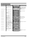
Motor Will Not
Stop Rotation
MIN Output Speed parameter set
too high.
Adjust MIN Output Speed parameter value.
Improper speed command. Verify control is receiving proper command signal at input terminals.
Verify control is set to receive speed command.
Speed potentiometer failure. Replace potentiometer.
Analog input common mode voltage
may be excessive.
Connect control input source common to control common (J1-1) to
minimize common mode voltage. Maximum common mode voltage at
terminals J1-4 and J1-5 is ±15VDC referenced to chassis common.
Analog offset trim set incorrectly. Re-run “Offset Trim” autotune test.
Adjust the Level 1 Input block, ANA CMD Offset parameter to obtain zero
speed.
Continued on next page.