


Section 1
General Information
4-16 Programming & Operation MN722
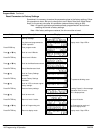
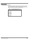
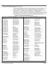
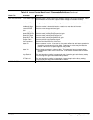
Table 4-4 Inverter Control Board Level 1 Parameter Definitions - Continued
Block Title Parameter Description
OUTPUT
(Continued)
Analog Output
#1 and #2
Two Analog 0-5VDC linear outputs may be configured to represent any of 19 conditions
as follows:
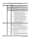
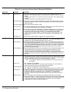
Condition Description
ABS Speed - Represents the absolute motor speed where 0VDC = 0 RPM and
+5VDC = MAX RPM.
ABS Torque - Represents the absolute value of torque where
+5VDC = Torque at CURRENT LIMIT.
Speed Command - Represents the absolute value of commanded speed where
+5VDC = MAX RPM.
PWM Voltage - Represents the amplitude of PWM voltage where
+5VDC = MAX AC Voltage.
Flux Current - Represents the actual portion of total current used for excitation.
5VDC= MAX flux current.
CMD Flux CUR - Represents the calculated value for flux current.
5VDC= MAX commanded flux current.
Load Current - Represents the actual portion of total current used to produce torque
(CW and CCW torque).
5V = Max. CW torque, 0V = Max. CCW torque.
CMD Load Current - Represents the calculated value of load current.
5V = Max. commanded load current.
Motor Current - Amplitude of continuous current including motor excitation current.
5VDC = Rated Current.
Load Component - Amplitude of load current not including the motor excitation
current. 5VDC = Rated Current.
Quad Voltage - Load controller output. Used to diagnose control problems.
Direct Voltage - Flux controller output. Used to diagnose control problems.
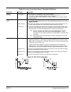
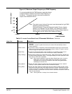
AC Voltage - A scaled AC waveform that represents the AC line to line motor
terminal voltage. 0V = Neg Peak PWM voltage. 2.5V centered.
5V = Pos Peak PWM voltage. At rated motor voltage, a full 0 to 5V
sinusoidal waveform should be present. This waveform should be at
or greater than the motor base frequency. (At half the motor base
frequency, a 1.25V to 3.75 sine wave is present.)
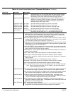
Bus Voltage - Bus voltage scaled to 0-5VDC. 5V = 1000VDC.
Torque - Bipolar torque output. 2.5V centered, 5V = Max Positive Torque,
0V = Max negative torque.
Power - Bipolar power output. 2.5V = Zero Power, 0V = negative rated peak
power, +5V = Positive rated peak power.
Velocity - Represents motor speed scaled to 0V = negative max RPM,
+2.5V = Zero Speed, +5V = positive max RPM.
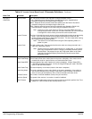
Overload - (Accumulated current)
2
x (time), Overload occurs at +5V.
PH 2 Current - Sampled AC phase 2 motor current. 2.5V = zero amps,
0V = negative rated peak amps, +5V = positive rated peak amps.
PH 3 Current - Sampled AC phase 1 motor current. 2.5V = zero amps,
0V = negative rated peak amps, +5V = positive rated peak amps.
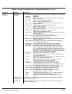
Process Feedback - Represents the selected Process Feedback signal.
2.5V centered, 5V = 100%, 0V = –100%.
Setpoint Command - Represents the selected Setpoint Command signal.
2.5V centered, 5V = 100%, 0V = –100%.
Position - Position within a single revolution. +5V = 1 complete revolution.
The counter will reset to 0 every revolution.
Serial – 0–5VDC level that indicates a value programmed by a serial
command.
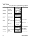
Analog #1 Scale &
Analog #2 Scale
Scale factor for the Analog Output voltage. Useful to set the zero value or full scale
range for external meters.
Position Band Sets the acceptable range in digital counts (pulses) at which the AT Position Opto
becomes active (turns on).